Return to Sheridan MECE21469D course guide. Tutoring coverage for this course must be confirmed before booking and payment.
From a load diagram to two support reactions
A distributed load acts along a length. Its arrows do not represent a collection of equal point forces: their heights show force per unit length. This lesson turns that diagram into an equivalent force at the correct position, then uses equilibrium to find the reactions.
First review torque and static equilibrium if perpendicular lever arms or moment signs are unfamiliar. You need rectangle and triangle areas, weighted averages and simple equations; calculus is optional. Allow about 40 minutes.
We use ideal, horizontal, rigid beams in static equilibrium. A pin at A can supply horizontal and vertical forces; a frictionless roller at B on a horizontal surface supplies only a vertical force. Neither support supplies a reaction couple. All applied loads here point downward; the beam’s weight is neglected unless explicitly included. These are learning models, not structural-design or safety calculations.
1. Height is intensity; area is force
Let measure distance rightward from A, in metres. Let be downward load intensity in N/m or kN/m. The loaded interval starts at and has length . The support span , from A to B, may be longer than . Let be the magnitude of the equivalent downward force and its position measured from A.
A small strip of width carries approximately force. Adding strips means finding the area under the intensity diagram. The equivalent force must preserve both total force and total moment:
The line of action passes through the centroid of the load-diagram area, not necessarily the centre of the beam or the middle of the loaded interval. For readers using calculus, and , provided . The geometry below is enough for every question here.
Unit check: ; multiplying force by position gives kN·m. Also . An intensity of 4 kN/m is not a force of 4 kN. The plotted vertical height represents intensity, not a physical height above the beam.
2. Uniform loading: use the loaded length
For constant intensity over , the diagram is a rectangle:
Draw a new free-body diagram: remove the distributed arrows and replace them by , then add . Here and are the signed horizontal and vertical reaction components at A; is the signed vertical reaction at B. Do not count both the original load and its replacement. With upward forces and counterclockwise moments positive, and only the stated vertical loads:
Thus and . The denominator is the distance between supports, not the loaded length.
Worked example 1: an offset rectangle
A and B are 6 m apart. A uniform downward load of 3 kN/m acts from m to m. The loaded length is m, so kN at m.
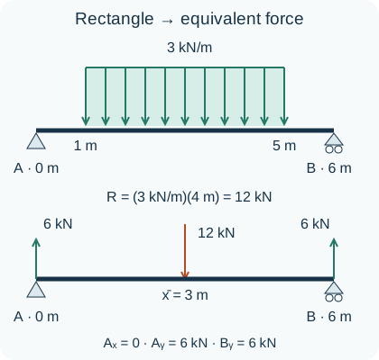
Taking moments about A gives , so kN upward and kN upward; . Check: , and about B, kN·m. Multiplying 3 kN/m by the whole 6 m beam would incorrectly load the two unloaded ends.
3. A triangular load: locate the taller end
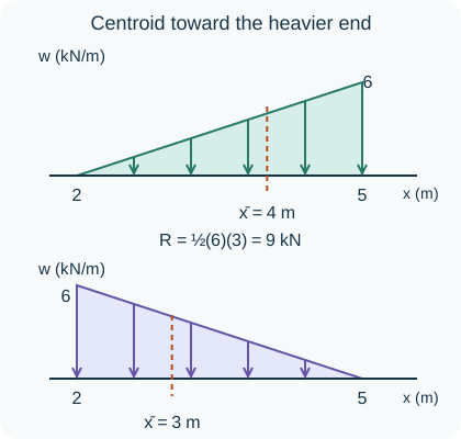
A linearly varying intensity from zero to makes a triangular diagram. Its force is half that of a rectangle with the same base and peak. Its centroid lies one-third of the loaded length from the taller end, or two-thirds from the zero end.
- Zero at the left, peak at the right: .
- Peak at the left, zero at the right: .
The stronger part of the load pulls the centroid toward itself. Reversing the triangle preserves its area and force but changes its moment.
Worked example 2: a triangle that starts away from A
On a 6 m support span, the intensity rises from zero at m to 6 kN/m at m. Here m, so kN and m. Hence kN and kN, both upward.
Check the increasing case: kN, and about B, kN·m.
Reverse the same triangle: its centroid is now m, giving kN. Check the reversed case about A: kN·m. A midpoint shortcut would accidentally work for neither triangle’s centroid; the second result is symmetric about the supports only because its centroid lands at the beam midpoint.
4. Combined loading: add forces and their moments
Split a trapezoid into a rectangle plus a triangle. Find each component’s magnitude and position , all from the same origin A. For several downward loads:
You may keep the component forces separate in the moment equation; finding a combined centroid is optional. Do not take an unweighted average of centroid positions unless the forces are equal. A point force is added directly in force units, without multiplying it by a loaded length.
Worked example 3: a trapezoid over part of a beam
Supports are at and m. From to m, the intensity increases linearly from 2 to 5 kN/m. Outside this interval it is zero. Split it into a 2 kN/m rectangle and a triangle whose extra peak is kN/m.
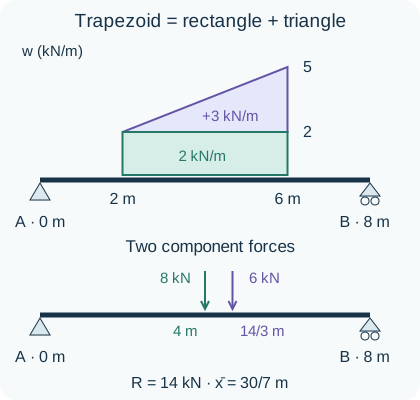
Rectangle: kN at m. Triangle: kN at m.
Therefore kN and kN upward, with . Check: the centroid m is between the component centroids and slightly right of the loaded interval’s midpoint, toward the stronger load. About B: .
Scope check: replacing a distributed load by one force preserves its external force and moment, so it works for whole-beam support reactions. It does not preserve the internal shear or bending moment at every cut. We are not computing stresses, deflections or allowable loads. A negative when upward is positive would require a downward contact force; an ordinary unrestrained roller cannot provide that, so the assumed contact model would need checking.
5. Eight practice and transfer questions
Use the same ideal support model throughout. Sketch the load area, label a common origin, and try each question before opening a hint.
A downward uniform load is 400 N/m over 2.5 m. Find its total force in N and kN.
Optional hint 1
Multiply intensity by loaded length, then convert force units.
Explained solution 1
N = 1 kN downward. N/m becomes N after multiplication by metres; 400 N would confuse intensity with force.
A uniform load of 2 kN/m acts from to m. Find , , and its signed moment about A at , with counterclockwise positive.
Optional hint 2
Find the interval length and add the offset to its local midpoint.
Explained solution 2
m, kN, and m. Its moment is kN·m (clockwise). The local midpoint 2 m is not the distance from A.
Over to m, a triangular downward load decreases from 3 kN/m to zero. Find its equivalent force and position.
Optional hint 3
Start one-third of the loaded length from the taller left end.
Explained solution 3
kN, at m. Placing it at 5 m would describe the reversed triangle, not this one.
A pin at and a roller at m support a beam loaded uniformly downward at 2 kN/m over its entire span. Find all reaction components.
Optional hint 4
First replace the load by one force at the midpoint.
Explained solution 4
kN at 2.5 m. From , kN upward; kN upward and . The frictionless roller on a horizontal surface has no horizontal reaction.
A 6 m span carries a load that rises from zero at A to 3 kN/m at B. A student puts its resultant at 3 m and obtains equal reactions. Correct the setup and find the reactions.
Optional hint 5
The triangle’s area and centroid require separate decisions.
Explained solution 5
kN, but m. Thus kN and kN upward. Equal reactions would put the resultant at the midpoint and fail the actual moment balance.
A beam has A at 0 and B at 10 m. Its load decreases linearly from 4 to 2 kN/m over to m, and is zero elsewhere. Find the reactions.
Optional hint 6
Split into a 2 kN/m rectangle and a triangle with peak 2 kN/m at the left.
Explained solution 6
The rectangle gives 12 kN at 5 m. The triangle gives 6 kN at m. Total load is 18 kN and moment magnitude about A is kN·m. Thus kN and kN upward, with . The larger left reaction agrees with the stronger left loading.
Transfer: A is at 0 and B at 8 m. A uniform downward load of 1.5 kN/m acts from 0 to 4 m; an additional 4 kN downward point force acts at 6 m. Find both vertical reactions and the combined resultant position.
Optional hint 7
The point force already has force units. Add its moment to the rectangle’s moment.
Explained solution 7
The rectangle gives 6 kN at 2 m. Hence kN and kN·m. Thus m, kN and kN upward. The unweighted average 4 m would be wrong because the two forces differ.
Transfer and retry: an 8 m beam has a pin at 0 and roller at 8 m. A uniform downward load acts over to m. Its measured ideal vertical reactions are 5 kN upward at each support. Find the intensity. If the same load patch moves to to m, find the new reactions.
Optional hint 8
Use the reaction sum to recover the total load, then move its centroid without changing its area.
Explained solution 8
Total load is kN, so kN/m. Initially the centroid is 4 m, consistent with equal reactions. After moving the patch, m, so kN and kN upward. Total force stays fixed while the moment increases.
Ready to move on? Explain why N/m is not N, why an offset must be added to a local centroid, and why reversing a triangle changes the reactions. If you missed one of these, retry questions 1, 2 or 5 with a labelled sketch.
Course context and next step
The official Sheridan MECE21469D outline (Winter 2026) includes distributed loading in force-system resultants and calculation of equilibrium reactions. This original practice resource targets those topics; it is not an official course handout or a complete course review.
For help setting up a distributed-load problem, explore mechanics tutoring. Tutoring sessions are currently offered in English.
Useful for
Work on the step you’re missing.
Tell us the subject and your preferred time. Nablio confirms the details by text or email.
Request a lesson