Stuck on a step? Text us Email us Request a lesson
Start with the path of the light. In this lesson, you will measure angles correctly, predict how a ray changes direction, and construct a lens image before using a lens equation. The focus is beginner geometric optics, using ideal thin lenses in air.
Need a refresher? Review angles, similar triangles, and right-triangle ratios with finding an angle.
On small screens, scroll diagrams horizontally to read every label. With a keyboard, press Tab to focus a diagram, then use the left and right arrow keys to scroll.
1. Draw the normal first
A ray is a line with an arrow showing the direction light travels. In a uniform transparent medium, rays travel in straight lines. At a boundary, first draw the normal: a line perpendicular to the surface at the point where the ray arrives.
The angle of incidence is between the incoming ray and that normal. Reflection and refraction angles are also measured from the normal, in their respective media. An angle given from the surface must be converted: angle from normal = 90° − angle from surface.
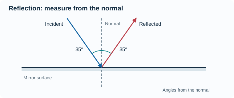
Reflection: equal angles, same medium
For a plane mirror, the reflected ray stays in the incident medium and obeys . Here each angle is 35° from the normal. The reflected ray is therefore 55° from the mirror surface.
On a rough surface, the local normals point in different directions. Each ray still obeys the reflection law, but the collection of reflected rays spreads out: diffuse reflection. A smooth mirror produces specular reflection.
Pause and try: A ray arrives at 25° to a mirror's surface. What are its incidence and reflection angles? Do not use 25° unchanged.
2. Refraction: predict, then calculate
Refraction is the change in direction that can occur when light crosses into a different transparent medium. Its refractive index is , where is the speed of light in vacuum and v is its speed in the medium. The index n has no units. For example, corresponds to .
For the transmitted ray, . Subscript 1 is the medium the light leaves; 2 is the medium it enters. Use your calculator's degree mode for angles given in degrees.
- A higher index on entry means bending toward the normal, for nonzero incidence.
- A lower index means bending away from the normal, if a transmitted ray exists.
- At normal incidence, and . The speed can change even though the direction does not.
Worked example: air into a higher-index material
Use for air, for the material, and .
- Predict: the second index is larger, so should be smaller than 45.0°.
- Calculate the sine: .
- Find the angle: from the normal.
- Check: 28.1° is smaller than 45.0°, matching the predicted bend. The result is an angle; 0.4714 is its sine.
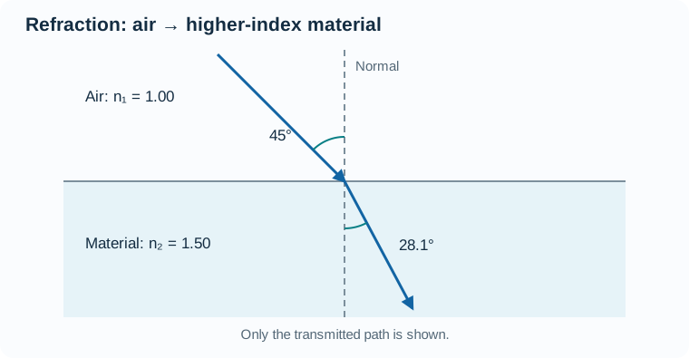
The figure shows the transmitted path only; some light can also reflect at the boundary.
Your retry: Keep the same two media, but change to 30.0°. Predict the bend, calculate , then find . A smaller incident angle should give a smaller refracted angle.
One important limit: Total internal reflection is possible only when light goes from a higher index to a lower index and its incidence angle exceeds the critical angle, . At the critical angle, the limiting refracted ray runs along the boundary. If Snell's law would require , there is no propagating refracted ray. For and , ; a 50° incident ray is totally internally reflected.
3. Build a lens image from one object point
Light from the tip of an object reaches a lens along many paths. We trace two convenient rays from the same tip. Where the outgoing rays meet is the image of that tip. Other object points form the rest of the image.
The principal axis is the lens’s line of symmetry, drawn horizontally here. The optical centre is where this axis crosses the thin lens.
The two foci lie on the axis, on opposite sides of the centre. Rays initially parallel to the axis converge at a focus after a converging lens; after a diverging lens, their backward extensions meet at a focus. In these diagrams, light travels left to right: is on the incoming side and on the far side. For this ideal thin lens in air, both foci are the same distance from the centre. This distance is positive; the focal length is positive for a converging lens and negative for a diverging lens.
In the ideal thin-lens model, for rays close to the principal axis:
- A ray through the optical centre continues straight.
- At a converging lens, an incoming ray parallel to the axis leaves through the focus on the far side.
- At a diverging lens, that parallel ray leaves as though it came from the focus on the incoming side. Extend it backward to show that focus.
Do not send every ray through a focus. The focal rule above applies specifically to a ray that arrives parallel to the axis.
A real image, in three steps
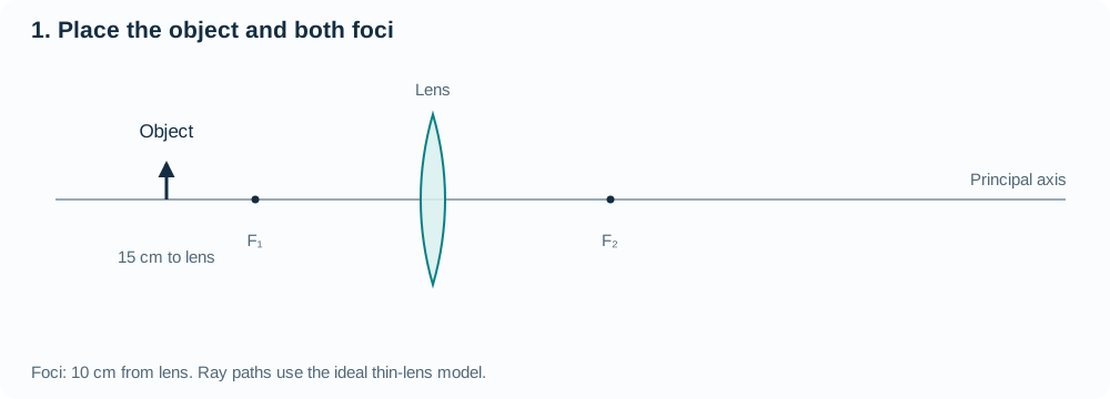
Use a converging lens whose foci are 10 cm from its centre. Put a 2 cm tall object 15 cm to the left. The object is between the near focus and twice the focal distance.
Step 1: place the object, axis and both foci. The object arrow starts on the principal axis. Draw the lens at its centre position, with and equally distant from it.
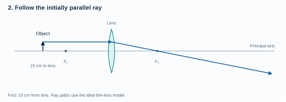
Step 2: trace the initially parallel ray. From the object tip, go parallel to the axis to the lens. After the lens, continue through the far focus . One ray alone does not yet locate the image.
Step 3: add the central ray. From the same tip, draw through the optical centre and continue straight. The two outgoing rays intersect below the axis. Put the image arrow's tip there and its base on the axis.
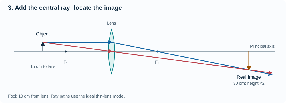
This construction gives a real, inverted, enlarged image: 30 cm from the lens on the opposite side, with a physical height of 4 cm. A screen at that location can catch the image. The figures use one common horizontal and vertical scale within the ideal model; the image position comes from the intersection, not from guessing where to place an arrow.
4. What changes when the object moves inside the focus?
Keep the same converging lens, but move the 2 cm object to 6 cm from it. Apply exactly the same two ray rules. This time the outgoing rays spread apart. They do not meet on the far side.
Extend those outgoing paths backward with dashed lines. Their extensions meet on the object's side, 15 cm from the lens. That is a virtual, upright, enlarged image, 5 cm tall.
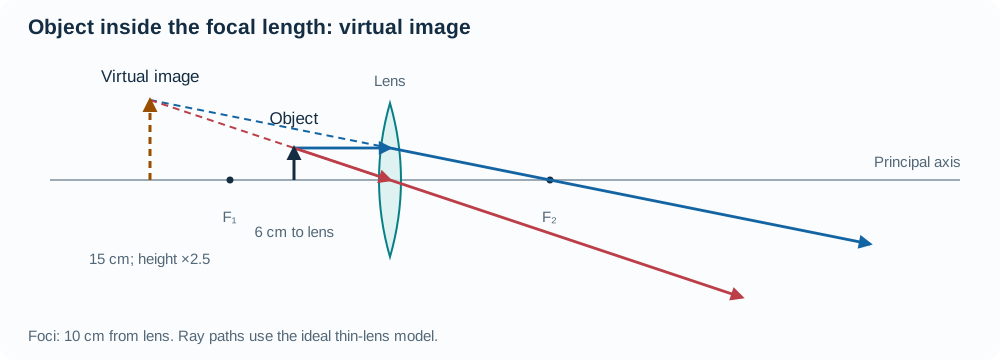
The dashed extensions show where the light appears to come from. Light does not travel backward along them. An eye receiving the outgoing rays can see the virtual image, but a screen placed at its apparent location cannot catch it. Thus, a converging lens does not always produce a real image.
Where a backward extension overlaps an actual incoming ray, the diagram keeps that physical segment solid.
5. A diverging lens uses the same method
For a diverging lens, the initially parallel ray spreads away from the axis. Its backward extension passes through the near focus . The central ray still continues straight in the thin-lens model.
With foci 10 cm from the lens and the same 2 cm object 15 cm away, the extensions locate a virtual image 6 cm from the lens on the object's side. It is upright and 0.8 cm tall, or 0.4 times the object height.
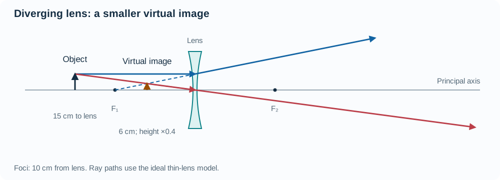
For a real object, a single diverging lens makes a virtual, upright, reduced image. Use the ray construction to explain the result, rather than memorising just the three adjectives.
6. Connect the diagram to quantities and signs
For the real-positive convention used here:
- : object distance from the lens; positive for the real objects in this lesson
- : image distance from the lens; positive for a real image on the far side, negative for a virtual image on the object's side
- f: focal length; positive for a converging lens, negative for a diverging lens
- and : object and image heights; positive above the axis, negative below it
- : linear magnification, with no units; its sign gives orientation and the absolute value of m gives the height ratio
Use consistent length units in . Centimetres work if all three lengths use centimetres. These signed distances are not all left-to-right coordinates: an object drawn left of the lens still has in this convention.
The real-image diagram has and . The inside-focus diagram has and . The minus signs mean different things: image side/type for , orientation for .
Ready for the algebra? Use the existing thin-lens worked example and retry. Keep your course's sign convention and its matching equation together if they differ from this one.
7. Try a fresh ray construction
Keep the converging lens with and an upright 2 cm object, but move the object to 20 cm from the lens. Use graph paper and one scale for all lengths.
- Place the object, centre and both foci. Which special position is the object at?
- Draw the initially parallel ray and the central ray, both from the object tip.
- Locate their intersection. Give the image's type, side, orientation and height relative to the object.
- Could a screen catch the image? Explain using the rays, not just the sign of a number.
Hint 1:
The object is at twice the focal distance.
Hint 2:
Your parallel ray must cross the far focus after the lens.
Hint 3:
Extend both physical outgoing rays until they meet; do not use backward extensions unless the outgoing rays fail to meet.
Answers and checks
- Reflection pause: incidence, then 65° reflection. Both angles are measured from the normal; the reflected ray is 25° from the surface.
- Refraction retry: , so . The ray bends toward the normal. Do not replace the sine relation with .
- Fresh construction: the object is at 2f. The two outgoing rays meet 20 cm on the far side and 2 cm below the axis: a real, inverted image of equal height. A screen catches it because actual outgoing rays converge at the image. In the stated convention, , and .
Continue with the optics subject hub. These fundamentals are a starting point; this lesson does not cover every mirror, optical device, or course requirement.
Sources
Topic scope: Québec Secondary V physics program, geometric optics and progression of learning, pp. 12–13. Dawson's 203-001-RE description includes reflection, refraction and lenses. Ray rules and model conventions: OpenStax reflection, refraction, and thin lenses. Examples and figures were created for this lesson.
Useful for
Work on the step you’re missing.
Tell us the subject and your preferred time. Nablio confirms the details by text or email.
Request a lesson