Stuck on a step? Text us Email us Request a lesson
One slit can produce several bright regions. Two slits can produce a row of fine fringes inside a broad, fading pattern. Count the openings first, then mark the distance that controls each feature: the width of one opening, a, or the centre-to-centre separation of two openings, d.
You will locate the dark boundaries of a single-slit central maximum, calculate ideal two-slit fringe spacing, and predict what changes when a slit dimension doubles. The examples are original practice, not an official examination or a claim about a particular course.
1. Read the aperture diagram
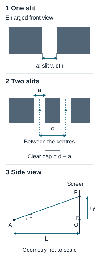
For a single slit, light from different parts of the same opening combines. For two slits, the contributions from the two openings combine too. Both patterns arise from superposition; the useful distinction is which parts of the aperture you are comparing.
A broad central bright region bounded by zeros is a single-slit feature. Closely spaced bright and dark fringes are a two-slit interference feature. Real two-slit patterns can show both.
Before calculating: a drawing labels a clear gap of 0.060 mm between two openings, each 0.020 mm wide. What is d? It is 0.080 mm: half a width, the clear gap, then half a width. The gap itself is not d.
2. State the model and quantities
Assume monochromatic light in a uniform medium, incident normally and in phase across the aperture. The long, parallel slits are uniformly illuminated; we study spreading across their widths. For two slits, assume identical widths and equal illumination with a stable relative phase of zero.
Use a far-field (Fraunhofer) pattern. For free propagation, a useful sufficient check is , where D is the full transverse aperture size: a for one slit, or d+a for this two-slit arrangement. A suitable lens can instead produce a far-field pattern in its focal plane; that configuration needs its own screen geometry. Being far from the aperture does not automatically make every observation angle small.
- : wavelength in the propagation medium, in metres (m).
- : width of each slit, in m.
- : centre-to-centre slit separation, in m, for two non-overlapping openings with a gap.
- : perpendicular distance from aperture plane to screen, in m.
- : signed screen position from the central axis, in m; positive above the centre in our side-view geometry.
- : signed angle from the central axis, positive toward positive y; use radians in small-angle approximations.
On a flat screen, . Near the centre, , so . Check before using this shortcut. If it is not small, retain the trigonometry. Remember and .
If wavelength is unfamiliar, review wavelength and period on wave graphs before continuing.
3. One slit: locate dark minima
For a uniformly illuminated slit, the far-field dark minima satisfy
Here n labels a diffraction minimum. Zero is excluded: straight ahead, the contributions add to form the central maximum. Only orders with reach a finite point on our screen.
At the first positive minimum, the edge-to-edge path difference is one wavelength. Pair each point in one half of the slit with the corresponding point in the other half: the paired paths differ by half a wavelength and cancel. Comparing only the two edges would miss this cancellation across the full opening.
For small angles,
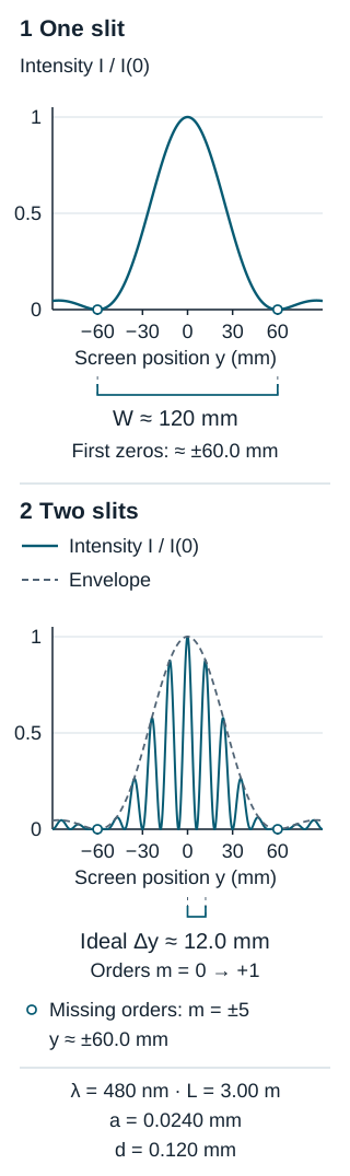
W is the full width of the central maximum between its first dark boundaries, from to . It is not the centre-to-first-minimum distance and not the full width at half maximum. The side maxima are weaker; do not treat them as equally bright copies of the centre.
4. Two slits: locate interference fringes
In the ideal narrow-slit model, constructive interference occurs when the path difference between the two slit centres is a whole number of wavelengths:
Here m labels an interference maximum, including the central bright fringe at m=0. The ideal dark interference fringes satisfy , with m any integer. These are different conditions from the single-slit minima.
Near the centre, successive ideal bright fringes have spacing
is the distance from one bright fringe to the next on the screen. It is not a signed position. Equal spacing is a small-angle approximation, not an exact statement across an arbitrarily wide flat screen.
5. Worked comparison: keep wavelength and screen distance fixed
Use and . Experiment A uses one slit of width . Experiment B uses two identical slits of that width with centre separation . Find A’s first dark positions and central width, then B’s ideal bright-fringe spacing.
Step 1: convert before substituting
Step 2: use a for the single slit
By symmetry, . The full central width is . The negative position marks the opposite side of the centre; the width is positive.
Step 3: use d for the two slits
The ideal m=+2 bright position is . The result is a position measured from the centre, twice the adjacent-fringe spacing.
Step 4: check the approximation and the units
At A’s first minimum, . Using gives 60.012 mm, about 0.020% above the approximation. The full two-slit aperture is , giving , much smaller than 3.00 m. The stated far-field model is appropriate here. In both screen formulas, the units reduce to .
6. Predict first, then calculate
Guided prediction
Keep wavelength and screen distance fixed. Double a in experiment A. Separately, double d in experiment B while keeping a fixed. Which pattern dimension halves in each case?
Hint
Identify the denominator before using numbers: W depends on a; ideal fringe spacing depends on d.
Check the reasoning
Doubling a to 0.0480 mm halves A’s central width to approximately 60.0 mm. Its first minima move to ±30.0 mm. Doubling d to 0.240 mm halves B’s ideal spacing to 6.00 mm; with a unchanged, its envelope still has first zeros near ±60.0 mm. These are separate changes.
Less help: infer an opening
A single slit produces a central maximum 80.0 mm wide between its first dark boundaries. The wavelength is 600 nm and L=2.00 m. Find a using the small-angle model.
Hint
The centre-to-first-minimum distance is half the given width. Rearrange .
Check the answer
. Using the full width as y₁ would incorrectly halve a. The edge ratio is , consistent with the small-angle approximation.
7. Real two-slit patterns have an envelope
Each slit has a finite width. Its diffraction changes the brightness of the two-slit fringes: fine interference structure sits inside a broad diffraction envelope. Increasing d at fixed a packs the fringes more closely; increasing a at fixed d narrows the envelope.
For our worked numbers, d/a=5. The nominal m=±5 interference maxima coincide with n=±1 diffraction minima. Those orders are missing: the envelope is zero there. The central envelope contains nominal orders −4 through +4.
The simple spacing formula locates ideal interference orders. Multiplying by a varying envelope can shift the actual local intensity peaks slightly, so do not claim exact measured peak spacing for finite-width slits.
Optional: the intensity model behind the diagram
For this ideal coherent, equally illuminated aperture, normalized intensity is
I is light intensity; I(0) is its central value, so the ratio has no units. Use the limiting value 1 for at zero. The squared sinc factor gives the envelope and the squared cosine factor gives interference. For a single slit, only the squared sinc factor remains after normalization.
8. Independent retry
Cover the answers. Monochromatic light has wavelength 540 nm and the screen is 2.40 m away. A single slit has width 0.0360 mm. A separate two-slit aperture has this same slit width and centre separation 0.180 mm. Assume the same far-field conditions.
- Find the single slit’s first dark positions and full central width.
- Find the ideal two-slit fringe spacing and the m=−2 bright position.
- Only the slit width doubles. What happens to the central diffraction width, the two-slit envelope width and the ideal fringe spacing?
- Why does setting n=0 in the single-slit minimum condition give the wrong interpretation?
Check all answers
1. ; dividing by gives . Thus .
2. ; .
3. Both central diffraction width and central envelope width halve to approximately 36.0 mm. Ideal fringe spacing stays 7.20 mm because d is unchanged.
4. At zero angle all parts of the opening contribute in phase, giving a maximum. The cancellation argument requires a nonzero integer n.
Check: the original first-minimum ratio is 0.0150. The exact trigonometric distance is 36.004 mm. For the original two-slit aperture, , below L by a factor of about 28.
If your answer differs, first check whether you used a or d, whether the question asks for a half-width or full width, and whether all lengths use the same unit.
Bring the diagram to tutoring
For optics tutoring or CEGEP waves and optics tutoring, bring your aperture sketch, your first equation and the step that is unclear. A tutor can help distinguish geometry, model choice and calculation. Share your current chapter so Nablio can confirm fit and availability. Sessions are offered in English.
Physics references
For further reading, see OpenStax University Physics Volume 3 on single-slit diffraction and finite-width double-slit patterns. The explanations, numerical exercises and figure specifications here were written for this lesson; no textbook figure or exercise is reproduced.
Useful for
Work on the step you’re missing.
Tell us the subject and your preferred time. Nablio confirms the details by text or email.
Request a lesson