Stuck on a step? Text us Email us Request a lesson
Two objects can interact without having the same forces on them. Learn to draw a separate force diagram for each object, connect their accelerations, and find the force between them. Then test when two stacked blocks stop moving together.
Start here if you can already write Newton’s second law for one object. For a first explanation of force diagrams or static and kinetic friction, review free-body diagrams and friction. This lesson develops the next step: deciding which objects can share an acceleration and which forces disappear when you combine their equations.
We describe motion relative to the room and ignore tipping and rotation in these examples. Let denote the magnitude of gravitational acceleration; use . Mass is measured in kilograms (kg), force in newtons (N), and acceleration in . Each example states its other assumptions.
1. Keep one object’s forces together
A system is the object or group you choose to study. An external force comes from outside its boundary. An internal force is an interaction between objects inside that boundary. The same contact force can be external for one cart and internal for the pair of carts.
For each diagram, name the receiving object first. Then ask what touches it or attracts it. Draw only forces acting on that object. A free-body diagram replaces the surroundings with force arrows; an arrow showing acceleration belongs beside the diagram, clearly labelled as acceleration.
If cart A pushes cart B to the right, B pushes A to the left with the same force magnitude. These are a Newton’s-third-law pair: they describe the same interaction but act on different objects. They cannot cancel on either cart’s individual diagram. They cancel when you add the two horizontal force equations using the same positive direction.
A cart’s weight and the track’s upward support force both act on the cart. Even when they balance, they are not a third-law pair. The partner of the track’s force on the cart is the cart’s force on the track.
2. Link the motion before solving
- Choose the system for the question. Use the group to find a shared acceleration; use one object to find an interaction force. A group shortcut needs a justified motion relation.
- Draw one force diagram per object and state the positive direction for each equation.
- Write the motion constraint: the relation imposed by maintained contact or rope length. Two objects being connected does not, by itself, prove that their acceleration vectors are equal.
- Write one force equation per object. Here the symbol Σ means “add the signed force components”; m is that object’s mass and a is its acceleration component along the selected axis.
- Solve the equations together, then check contact, rope tension, and any no-slip assumption. A result outside the model’s allowed range means the model must change.
Two carts that stay pressed together on a straight track share an acceleration along the track. Two masses on opposite ends of a taut, nonstretching rope over one fixed pulley move equal distances in opposite vertical directions. Their acceleration magnitudes are equal, but their vertical acceleration components have opposite signs if you use one common upward axis.
Keep three reasons separate: equal-and-opposite interaction forces follow from Newton’s third law; equal tension along the modelled rope follows from ideal-rope and ideal-pulley assumptions; the relation between accelerations follows from geometry and rope length.
3. Worked example: two carts in contact
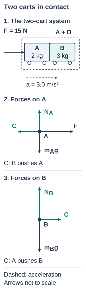
Cart A, with mass , is immediately to the left of cart B, with mass . A horizontal force pushes A to the right. They start together on a level track with negligible resistance and remain in contact. Find their acceleration and the contact force. Take right as positive.
Read the diagram in words
A 15 N force pushes a 2 kg cart A into a 3 kg cart B. Separate diagrams show applied force right and contact force left on A, contact force right on B, and balanced vertical weight and track-normal forces on each cart.
The dashed boundary encloses A and B; the applied 15 N push enters from outside. Right is positive. In the separate diagrams, A receives F right, C left, track normal N_A up and weight m_A g down. B receives C right, track normal N_B up and weight m_B g down. C is 9.0 N on each cart. The two C forces form a third-law pair on different objects. Neither cart’s weight and normal form a third-law pair. F − C = m_A a and C = m_B a give a = 3.0 m/s². A dashed acceleration arrow is outside the force diagrams. Solid arrows are forces; arrow lengths are schematic.
Let be the nonnegative magnitude of the contact force. A receives the applied force to the right and contact force to the left. B receives contact force to the right. Each also has its own weight downward and its own track normal upward; these vertical forces balance. “Normal” means perpendicular to the contacting surface.
The shared horizontal acceleration is a. The separate equations are:
Add the equations. The contact terms cancel because they are internal to the two-cart system:
Return to B alone to find the force that accelerates it:
The contact force is 9.0 N right on B and 9.0 N left on A. A still has a 6.0 N net force right, consistent with its smaller mass and the same acceleration. The 15 N applied force is external; it is not the force A transmits to B.
Model check: ordinary contact can push but cannot pull. Here C is positive, so maintained contact is consistent. If a proposed motion required a negative contact magnitude, separate the carts and reconsider their accelerations.
4. Worked example: two hanging masses
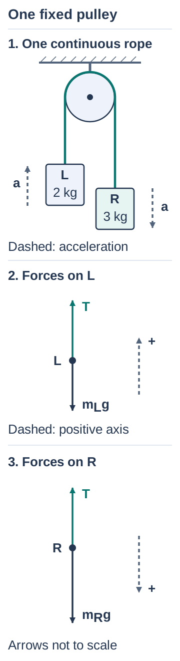
A left mass and a right mass hang from one rope over a fixed pulley. They are released from rest, with space to move freely. The rope stays taut, does not stretch, and has negligible mass. The pulley has negligible rotational inertia and a frictionless axle. These are the ideal-pulley assumptions used here. Find the acceleration and rope tension.
Read the diagram in words
Two hanging masses share one rope over a fixed pulley: 2 kg on the left and 3 kg on the right. Tension points upward on each mass. The left acceleration and positive axis point up; the right acceleration and positive axis point down.
The pulley axle is fixed to the ceiling. One taut rope runs vertically up from L, over the upper semicircle of the pulley and vertically down to R. L is 2.0 kg and R is 3.0 kg. Each separate force diagram has exactly two forces: T up and weight down. A separate dashed local positive axis points up for L and down for R. T = 23.52 N; the weights are 19.6 N and 29.4 N. Thus T − m_Lg = m_La and m_Rg − T = m_Ra, with a = 1.96 m/s². Equal tension follows from the ideal model; equal acceleration magnitudes follow from fixed rope length. The two upward forces T are not a third-law pair. The scene’s dashed arrows show acceleration, not extra forces. Arrow lengths are schematic.
Tension is the pulling force the rope exerts, directed along the rope and away from the mass. Under these assumptions its magnitude is the same on both sides. Each mass has only two forces: tension upward and weight downward. Take up as positive for L and down as positive for R. Let be their shared positive acceleration magnitude for the motion being tested.
The fixed rope length makes the left mass rise as far as the right mass falls. It supplies the common a in these opposite local directions. Adding the scalar equations eliminates T:
R accelerates down and L accelerates up. Use the left mass to find the tension:
The tension lies between the two weights, 19.6 N and 29.4 N. This makes the left net force upward and the right net force downward. The falling mass accelerates more slowly than free fall because tension reduces its downward net force.
Why did the tension disappear?
The two upward rope forces on the masses are not a third-law pair. Each is paired with that mass’s force on the rope. We chose up as positive on the left and down as positive on the right. T therefore enters one equation positively and the other negatively. The equal tensions cancel when we add these equations. This sum uses two local axes. It is not one global vertical force equation for objects moving together: the hanging masses accelerate in opposite directions.
Do not carry the ideal model into a different setup without checking it. A pulley with appreciable rotational inertia can need different tensions on its two sides. A slack rope does not impose the taut-rope motion constraint.
5. Worked example: when stacked blocks slip
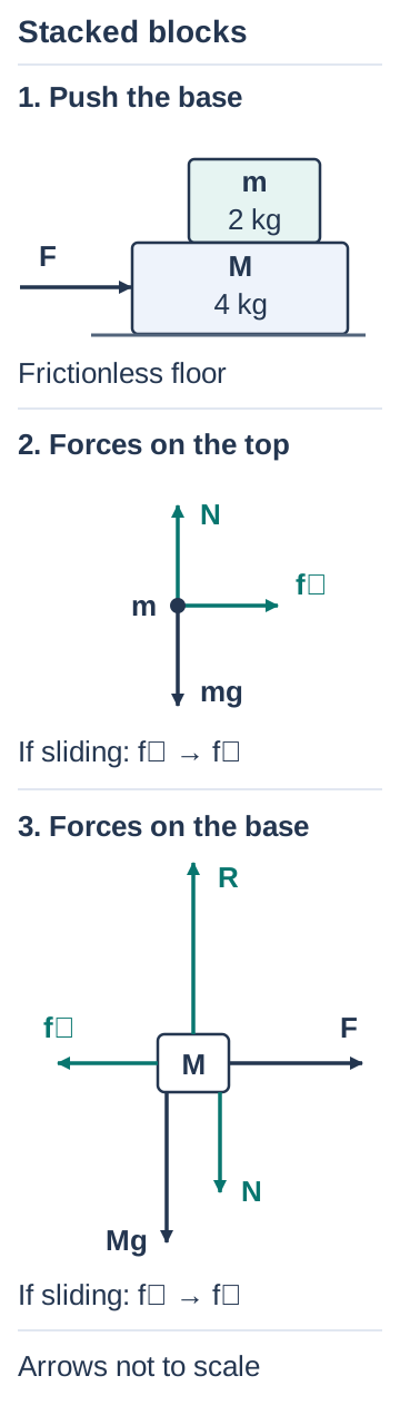
A top block has mass ; its base block has mass . The floor under the base is frictionless. A horizontal force pushes only the base to the right. Between the blocks, the static-friction coefficient is and the kinetic-friction coefficient is . The blocks initially rest together. They stay flat, maintain vertical contact, and do not tip. Find the largest F that allows them to move together.
Read the diagram in words
A 2 kg block rests on a 4 kg base pushed right on a frictionless floor. The top receives normal N up, weight mg down, and friction right. The base receives floor normal R up, its weight Mg and contact normal N down, push F right, and friction left.
A top block m = 2.0 kg sits on a base M = 4.0 kg. F pushes only the base right; the floor has no friction. The top’s isolated diagram contains N upward, mg downward and static friction fₛ right. The base’s diagram contains floor normal R upward, its own weight Mg downward, the top’s normal N downward as a separate offset arrow, F right and fₛ left. N = mg, R = (M + m)g, fₛ = ma and F − fₛ = Ma while the blocks do not slip. The normal pair and friction pair act on different blocks. After sliding starts in this example, replace fₛ with fₖ on both diagrams; the same directions apply while the base slides right beneath the top. Arrow lengths are schematic and must not be used as numerical data.
Let be the normal-force magnitude between the blocks, the floor’s normal force on the base, and the static-friction magnitude between the blocks. No vertical acceleration gives for the top and for the base. The upper contact normal acts up on the top and down on the base. Friction acts right on the top and left on the base.
First suppose there is no relative slipping. This means the blocks share a horizontal acceleration a; it does not mean they are stationary relative to the room. The two horizontal equations are:
The top needs friction to accelerate. Compare that required friction with the available static limit:
The maximum no-slip acceleration and maximum push are therefore:
For F = 12 N, the common acceleration is 2.0 m/s² and the required friction is 4.0 N. The available static maximum is 5.88 N, so the no-slip assumption is consistent. The actual static friction is 4.0 N, not its 5.88 N maximum.
What changes above the threshold?
Now apply to the blocks initially at rest. The common-acceleration guess would require 8.0 N of friction, which exceeds 5.88 N. The base slips right beneath the top. Use kinetic friction, of magnitude , and give the two blocks separate accelerations (top) and (base), both measured positive right.
Both accelerate right, but the base accelerates faster. The top therefore slips left relative to the base. Friction on the top still points right: it opposes relative sliding at the contact. These equations apply while that sliding continues and the blocks still overlap. There is no single common acceleration to put into the two-block force equation after slipping starts.
6. Try four questions
Use g = 9.8 m/s² throughout. Draw the forces and state the motion relation before opening a hint. The questions move from identifying interactions to testing a model and changing it.
Question 1: which forces belong together?
Two carts A and B stay in contact on a level, frictionless track while a hand pushes A toward B. Identify (a) the partner of A’s contact force on B, (b) whether that pair is internal for the system A + B, and (c) whether A’s weight and the track’s force on A are a third-law pair. Explain why the two carts’ net forces need not have the same magnitude.
Hint
Name the object exerting each force and the object receiving it. A third-law pair swaps those two objects.
Solution 1
(a) B’s contact force on A is the partner; the two have equal magnitudes and opposite directions. (b) Both objects are inside A + B, so the pair is internal. For A alone, B’s contact force is external. The hand’s push remains external to A + B. (c) No: weight and track force both act on A. The weight’s partner is A’s gravitational force on Earth; the track force’s partner is A’s force on the track. The carts share an acceleration while contact is maintained, but each net force is its own mass times that acceleration. Different masses can therefore have different net forces.
Question 2: push from the other side
On a level, frictionless track, cart A (1.5 kg) is left of cart B (2.5 kg), initially at rest and touching. First push A right with 10 N. Find the acceleration and contact force. In a separate trial with the same arrangement at rest, push B left with 10 N. Find them again. Does equal push magnitude imply equal contact force?
Hint
Use both carts for acceleration. Then isolate the cart that does not receive the hand’s push.
Solution 2
Both trials have total mass 4.0 kg, so the acceleration magnitude is:
In the first trial both accelerate right. B receives only the horizontal contact force, so its magnitude is:
In the second trial both accelerate left. A is now the cart accelerated only by contact, so:
The contact force changes because it accelerates a different unpushed cart. Within either trial, the contact forces on A and B still form an equal-and-opposite pair. Both computed magnitudes are positive, consistent with the carts staying pressed together.
Question 3: a cart pulled by a hanging mass
A 3.0 kg cart rests on a frictionless horizontal table. A horizontal rope runs from the cart to a fixed ideal pulley at the right-hand edge, then vertically down to a hanging 1.0 kg mass. The taut rope has negligible mass and does not stretch; the pulley has negligible rotational inertia and axle friction. Released from rest, the cart moves toward the pulley. Find the acceleration of each object and the tension before either reaches an obstruction.
Hint
Take right as positive for the cart and down for the hanging mass. What happens to the vertical rope segment when the horizontal segment shortens?
Solution 3
Let be the cart’s mass and the hanging mass. The fixed rope length makes their acceleration magnitudes equal to a. The cart has tension right, weight down and table normal up. Its vertical forces balance. The hanging mass has weight down and tension up. Thus:
Add and solve, then return to the cart:
The cart accelerates right and the hanging mass down. T is less than the hanging weight, 9.8 N, which leaves a downward net force. Their acceleration magnitudes match because of rope length; their acceleration directions differ.
Question 4: test the shared-acceleration model
A 1.5 kg block sits on a 3.5 kg base on a frictionless floor. Between the blocks, the static-friction coefficient is μs = 0.40 and the kinetic-friction coefficient is μk = 0.25. Both start at rest, remain flat and do not tip. A horizontal force pushes only the base right. (a) For a 15 N push, do the blocks move together? Find the acceleration and friction. (b) Find the greatest push that allows no slipping. (c) In a new trial starting from rest, apply 25 N. Find each acceleration while the blocks slide relative to one another and remain in contact.
Hint
For each proposed shared acceleration, calculate the friction the top would need. Compare with the static maximum before using a common acceleration in the final answer.
Solution 4
Let denote the top mass and the base mass. The normal between them is . The static maximum is:
(a) The no-slip guess gives:
Since 4.5 N is below 5.88 N, they move together. Friction acts right on the top and left on the base. It is static because there is no relative sliding.
(b) At the no-slip limit:
(c) A common acceleration would be 5.0 m/s² and would require 7.5 N of friction, exceeding 5.88 N. The base slips right under the top. Use kinetic friction:
The top acceleration and base acceleration are:
Both point right. The greater base acceleration is consistent with the assumed sliding direction. The friction forces have the same magnitude on the two blocks, but their accelerations differ. These results end when the stated contact or sliding conditions change.
7. Optional check: not every pulley gives equal accelerations
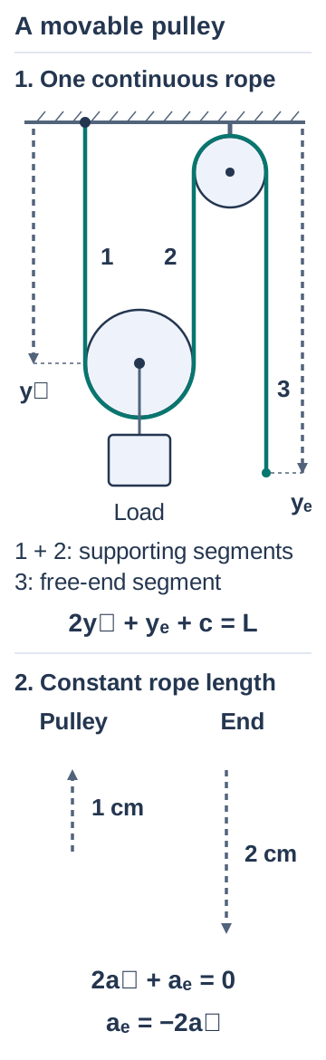
One rope end is fixed to the ceiling. The rope runs down around a movable pulley carrying a load, then up over a fixed ceiling pulley and down to a free end. The rope stays taut and does not stretch. The pulley moves only vertically, and all three changing straight rope segments stay vertical: the two beside the movable pulley and the one ending at the free end.
Read the diagram in words
A rope is fixed to the ceiling, runs under a movable pulley carrying a load, over a fixed ceiling pulley, and down to a free end. Two changing rope segments support the movable pulley; one changing segment leads to the free end.
One rope end is anchored at the ceiling. The rope runs down segment 1, under the movable pulley, up segment 2, over the fixed upper pulley and down segment 3 to a free end. The load is attached to the movable pulley axle, not to a rope end. All three changing straight segments are vertical. Downward positions yₚ and yₑ are measured from the same fixed ceiling reference, using separate dashed dimension lines. Fixed wrap lengths and coordinate offsets are included in c: 2yₚ + yₑ + c = L. Segments 1 and 2 each shorten by 1 cm when the movable pulley rises 1 cm; segment 3 lengthens by 2 cm and the free end descends 2 cm. Dashed arrows in the second panel indicate displacements, not forces. Differentiation gives 2aₚ + aₑ = 0 and aₑ = −2aₚ for signed downward accelerations.
Let be the movable pulley’s downward position and the free end’s downward position, each measured from a fixed horizontal reference. Let be the rope’s fixed total length and the constant contribution from fixed rope portions and the geometric offsets in these position measurements. The length relation is:
If the movable pulley rises 1 cm, each supporting segment shortens by 1 cm. The free-end segment must therefore lengthen by 2 cm: the free end moves down 2 cm. The same fixed ratio holds for velocities and accelerations.
With and the signed downward accelerations of the pulley and free end:
The free end’s acceleration magnitude is twice the movable pulley’s and its direction is opposite. A single rope does not guarantee equal acceleration magnitudes. Sketch the changing rope segments before writing the constraint.
8. Check your method, then choose the next step
- Can you name the object receiving every force?
- Can you identify the assumption that links the accelerations?
- Did you return to one object to find the contact force or tension?
- Did you check that contact, tension and friction stay within the chosen model?
Check diagrams and equations with a tutor
Bring a problem you are stuck on. You do not need to have started a solution. You can start from the question with your tutor, draw the forces on each object and explain how the rope or contact links their motion. If you already have a solution attempt, your tutor can help you find and correct the first step that does not follow from the diagram or assumptions. Then try a similar problem yourself, including a check for slipping. Ask about mechanics tutoring.
Course connections
This topic practice can support work on Newton’s laws and interacting objects in Marianopolis 203-AS1-MS Mechanics and 203-SN1-RE Mechanics. Use your current course outline to decide which models and depth are relevant.
For more work on choosing and drawing forces, return to free-body diagrams and friction. For questions about speed after a displacement or a collision, compare methods in work, energy or momentum.
Useful for
Work on the step you’re missing.
Tell us the subject and your preferred time. Nablio confirms the details by text or email.
Request a lesson