Stuck on a step? Text us Email us Request a lesson
For course topics and one-to-one help, see Concordia PHYS 205 tutoring.
1. Keep three choices separate
Kirchhoff’s laws turn a circuit drawing into equations. The difficult part is often the first sign, before any arithmetic. A reliable setup separates the reference direction of a current, the direction in which you walk around a loop, and the marked polarity of each voltage source. Once those are fixed, every term has a reason.
By the end, you should be able to write a junction equation, build a loop equation one component at a time, and explain a negative current without changing the circuit. You will need Ohm’s law and basic linear equations. The examples use ideal wires, positive resistances that obey Ohm’s law, ideal voltage sources and steady direct current (DC). Currents and source voltages are constant; wire resistance and source internal resistance are neglected. There are no charging capacitors, switching transients or changing magnetic flux through the loops in this model.
- Current reference: choose an arrow for each unknown branch current. A positive answer follows that arrow; a negative answer goes against it. We use conventional current, the direction positive charge would move.
- Loop walk: choose either direction around a closed path. This is a bookkeeping route, not another current. You may walk against a branch current.
- Source polarity: copy the + and − terminals from the drawing. Choosing an arrow does not change those terminals. The longer line in a battery symbol marks the positive terminal.
A node is a connected region of ideal wire at one potential. A junction is where current can split or combine. A branch is a path between junctions; components in series along that path share its current. A loop is a closed path that brings you back to your starting point.
2. Balance current at a junction
At a steady junction, charge does not accumulate. Kirchhoff’s current law (KCL), also called the junction rule, therefore balances the currents:
Sum entering = sum leaving.
For an arrow I₁ into a junction and arrows I₂ and I₃ out of it, write
.
Here I₁, I₂ and I₃ are signed currents in amperes (A). You may instead write I₁ = I₂ + I₃. Keep the arrow convention when you substitute a negative result. The equation describes conservation of charge, so a resistor does not “use up” current. The same steady current enters and leaves a resistor; electrical energy can be transferred to thermal energy.
You can even choose all reference arrows away from one node. Then their signed sum is zero. Except when all currents vanish, at least one answer must be negative. That tells you which branch actually brings current into the node.
3. Assign potential rises and drops around a loop
Let V mean electric potential, in volts (V). For each step, define the potential change as final minus initial:
.
Kirchhoff’s voltage law (KVL), also called the loop rule, says that the signed changes add to zero on returning to the same point. A positive ΔV is a rise; a negative ΔV is a drop. For a resistor, R is its resistance in ohms (Ω) and I is its signed reference current. For an ideal source, ℰ is its positive voltage magnitude.
| Component and traversal | Term in the loop equation |
|---|---|
| Resistor, with its reference-current arrow | −IR |
| Resistor, against its reference-current arrow | +IR |
| Ideal source, from − terminal to + terminal | +ℰ |
| Ideal source, from + terminal to − terminal | −ℰ |
| Ideal connecting wire | 0 V |
The resistor rules use the reference arrow, even if I later turns out to be negative. For instance, −IR becomes a positive potential change when I is negative. Along the actual conventional current through a positive resistor, potential decreases. A source’s sign, however, comes from the terminals you cross, independent of any current arrow.
Units: volts belong in a loop equation; amperes belong in a junction equation. Since A × Ω = V, IR has the right units for a potential change. Convert prefixes before substituting: 1 kΩ = 1000 Ω and 1 mA = 0.001 A. For example, 6 V ÷ 1500 Ω = 0.004 A = 4 mA.
4. Write the equations before calculating
- Read the connections. Mark the junctions and the fixed source polarities. A bend in a wire adds no component.
- Choose current arrows. Use one signed unknown per branch, keeping the same arrow everywhere it appears.
- Write the junction balance. Choose entering positive or leaving positive, and use it consistently.
- Choose enough independent loops. State the path and walk direction for each. List every crossed component in order.
- Solve the simultaneous equations. Reversing a loop gives the negative of the same equation, not an additional independent equation.
- Interpret and verify. Report the physical current directions, then substitute the signed answers into the original junction and loop equations.
“Independent” means an equation adds information that cannot be obtained from the others. In the three-branch circuit below, one junction equation and two independent loop equations are enough for three unknown currents. A second junction equation would repeat the same current balance.
5. Worked example with two opposing sources
The single loop has a 12 V source on the left, a 4 V source on the right, a top resistance R₁ = 2 Ω and a bottom resistance R₂ = 6 Ω. Both sources have their positive terminal at the top. Find the steady current. All values in this lesson are chosen ideal-model values; retain exact fractions until the final result.
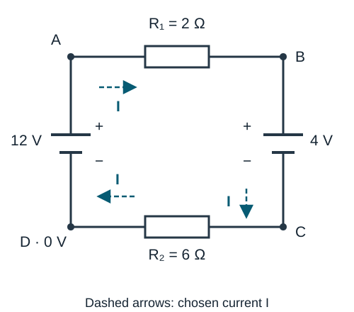
Set the references and write the loop
Choose current I clockwise. Walk D → A → B → C → D, also clockwise. Starting at D: cross the left source from − to +, cross R₁ with I, cross the right source from + to −, then cross R₂ with I. Calling the source magnitudes ℰ₁ and ℰ₂ gives
.
.
Rearrange before dividing: I(R₁ + R₂) = ℰ₁ − ℰ₂. Therefore I = 8 V ÷ 8 Ω = 1 A clockwise. The sources oppose each other in this traversal; adding 12 V and 4 V would ignore their marked polarities.
Check the answer in two ways
The original loop gives 12 − 2 − 4 − 6 = 0, with every term in volts. Set the reference potential at D to 0 V. Following the same route, the node potentials are A: 12 V, B: 10 V, C: 6 V, then D: 0 V. The reference fixes the potential labels without changing any current.
Now walk D → C → B → A → D while keeping the same clockwise current arrow. Both resistors are crossed against I, and both source crossings reverse:
.
Substitution gives 6 + 4 + 2 − 12 = 0 V. Reversing the walk changed every sign, but it did not change the physical answer.
6. Worked example with a negative branch current
Now connect three branches between A and B. Branch 1 contains R₁ = 2 Ω and a 12 V source in series. Branch 2 contains R₂ = 4 Ω and a 6 V source in series. Branch 3 contains only R₃ = 4 Ω. Both sources have their positive terminal above their negative terminal. Determine all three steady currents.
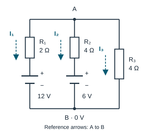
Keep all three current references downward
Choose I₁, I₂ and I₃ from A to B, as drawn. The junction equation at A is
. (1)
Let ℰ₁ = 12 V and ℰ₂ = 6 V. For the first loop, go down branch 1 and up branch 2. The two resistor crossings have opposite relationships to their arrows:
. (2)
For the second loop, go down branch 2 and up branch 3:
. (3)
The source signs come from their terminals. Down branch 1 or 2, the source crossing is + to −; on returning up branch 2 it is − to +.
Solve only after the signs are fixed
With the given values, equation (2) becomes −(2 Ω)I₁ + (4 Ω)I₂ − 6 V = 0 V. Thus I₁ = 2I₂ − 3 A. Equation (3) gives I₃ = I₂ + 1.5 A. Substitute both into equation (1):
.
Hence 4I₂ = 1.5 A. The signed answers are
- I₁ = −2.25 A: actual current 2.25 A from B to A, up branch 1.
- I₂ = +0.375 A: actual current 0.375 A from A to B, down branch 2.
- I₃ = +1.875 A: actual current 1.875 A from A to B, down branch 3.
The negative I₁ is a direction result, not a failed calculation. Keep its sign in every check made with the original arrows. If you redraw its arrow upward, give that new reference a new symbol and rewrite the affected equations.
Verify the junction and both loops
- Junction A, in amperes: −2.25 + 0.375 + 1.875 = 0.
- Loop (2), in volts: +4.5 − 12 + 6 + 1.5 = 0.
- Loop (3), in volts: −1.5 − 6 + 7.5 = 0.
For a second check, define U = VA − VB, the potential of A relative to B. This U is a voltage, not an energy. A traversal from A to B therefore has ΔV = −U. Each complete branch must give the same value of U:
.
Numerically, −4.5 + 12 = 1.5 + 6 = 7.5 V. A separate node-voltage equation is (U − 12 V)/(2 Ω) + (U − 6 V)/(4 Ω) + U/(4 Ω) = 0 A, which also gives U = 7.5 V. This checks the result without reusing the loop elimination.
With B at 0 V, A is at 7.5 V. The junction between R₁ and the 12 V source is at 12 V, so the actual current through R₁ goes upward from 12 V toward 7.5 V. This confirms the meaning of the negative I₁. Notice also that the complete branches share a voltage; the three resistors alone are not all in parallel, because their lower terminals are not all the same node.
7. Try five questions with hints and solutions
Write your arrows and equations before opening a solution. In questions 4 and 5, reuse Figure 2 with only the stated change.
Question 1 · Read the crossing
A resistor has R = 8 Ω and reference current I = +0.25 A pointing left to right. What is ΔV when you cross it left to right? What about right to left? Separately, what is ΔV when crossing an ideal 9 V source from + to −?
Show a hint
Compare the resistor crossing with the current arrow. For the source, look only at the terminals.
Show the solution
Left to right: ΔV = −IR = −2 V. Right to left: ΔV = +IR = +2 V. Across the source from + to −: ΔV = −9 V. The source answer does not require a current value or direction.
Question 2 · Interpret a signed junction result
A known 0.60 A enters a junction, and a known 0.15 A leaves it. A third current Ib has its reference arrow pointing into the junction. Find Ib and state its actual direction.
Show a hint
With entering currents positive, write 0.60 A + Ib − 0.15 A = 0 A.
Show the solution
Ib = −0.45 A, so 0.45 A actually leaves the junction. In physical directions, 0.60 A enters and 0.15 A + 0.45 A leaves. The reference arrow stays unchanged while solving.
Question 3 · Rebuild the single-loop equation
In Figure 1, change the left source to 9 V, the right source to 3 V, R₁ to 3 Ω and R₂ to 9 Ω. Keep both source polarities and the clockwise current reference. Find I, then check the loop.
Show a hint
Use the same traversal D → A → B → C → D. The equation structure is unchanged; replace the four given values.
Show the solution
9 V − I(3 Ω) − 3 V − I(9 Ω) = 0 V. Thus I = 6 V ÷ 12 Ω = 0.50 A clockwise. The voltage balance is 9 − 1.5 − 3 − 4.5 = 0. In this series loop, both resistors carry the same 0.50 A, despite their different voltage drops.
Question 4 · Reverse only one current reference
For the original Figure 2, redefine only the left-branch current as J₁ pointing upward from B to A. Keep I₂ and I₃ downward. Write the junction equation and the loop going down branch 1, then up branch 2. What is J₁?
Show a hint
J₁ = −I₁. Going down R₁ now means walking against its new current reference, so its resistor term changes sign. Source polarities do not change.
Show the solution
The junction equation is −J₁ + I₂ + I₃ = 0. The loop is +R₁J₁ − ℰ₁ + ℰ₂ + R₂I₂ = 0. Therefore J₁ = +2.25 A upward, while I₂ = +0.375 A and I₃ = +1.875 A are unchanged. Checks: −2.25 + 0.375 + 1.875 = 0 A and 4.5 − 12 + 6 + 1.5 = 0 V. The physical circuit is identical.
Question 5 · Change a source and solve again
Return to all three downward reference arrows in Figure 2. Replace only the 6 V source with an ideal 18 V source of the same polarity. Find I₁, I₂ and I₃. Do not assume that their signs remain the same.
Show a hint
The equations are I₁ + I₂ + I₃ = 0, −(2 Ω)I₁ − 12 V + 18 V + (4 Ω)I₂ = 0 V, and −(4 Ω)I₂ − 18 V + (4 Ω)I₃ = 0 V. Alternatively, use U = VA − VB to express all three currents.
Show the solution
The node-voltage equation is (U − 12 V)/(2 Ω) + (U − 18 V)/(4 Ω) + U/(4 Ω) = 0 A. Multiplying by 4 Ω gives 2(U − 12 V) + (U − 18 V) + U = 0 V, hence U = 10.5 V.
Then I₁ = −0.75 A, I₂ = −1.875 A and I₃ = +2.625 A. Both source branches now carry actual current upward; the right branch carries it downward. Checks: −0.75 − 1.875 + 2.625 = 0 A; 1.5 − 12 + 18 − 7.5 = 0 V; and 7.5 − 18 + 10.5 = 0 V.
8. Find a sign error before restarting
- A source sign changes when you redraw a current arrow: restore its marked polarity. Only changing the source terminals you cross changes its loop sign.
- The same resistor always has a minus sign: compare each loop walk with that resistor’s reference arrow. Different loops may cross it differently.
- Every solved current is forced positive: keep the signed answers until you have interpreted them against the arrows.
- You have three equations but cannot solve three currents: check whether a loop was merely reversed or whether two junction equations say the same thing.
- A junction check passes but a loop fails: inspect the failed loop’s traversal, polarities, resistance values and arithmetic. Passing one law is not sufficient.
- An answer is off by 1000: look for a missed conversion between A and mA or Ω and kΩ.
For your next course exercise, stop after writing the independent equations. Beside each voltage term, note “with arrow,” “against arrow,” “− to +” or “+ to −.” Then calculate and verify. If you bring this setup to a tutor, the first inconsistent term shows exactly where to focus.
9. Course connection and references
For PHYS 205 Electricity and Magnetism, use your course outline to choose the circuit methods to practise.
The figures, numerical examples and practice questions here are original and independent of Concordia. For a separate explanation of fields and potential, see electric field versus electric potential.
- Concordia University: official Physics course descriptions — PHYS 205 course description.
- OpenStax University Physics, volume 2, section 10.3: Kirchhoff’s Rules — further reading on junction and loop laws.
- MIT OpenCourseWare: Circuits, chapter 6 — additional discussion of signed circuit variables and node equations.
Useful for
Work on the step you’re missing.
Tell us the subject and your preferred time. Nablio confirms the details by text or email.
Request a lesson