Stuck on a step? Text us Email us Request a lesson
For course topics and one-to-one help, see Concordia PHYS 205 tutoring.
The same capacitor can lose stored energy when its plates move apart, or gain it. The result depends on what remains connected. Start by identifying the connections and what can exchange charge or energy.
Before you start: be comfortable with powers of ten, rearranging equations and interpreting a potential difference. The main reasoning is algebraic; one optional integral explains the energy formula.
By the end: you should be able to distinguish charge, voltage, capacitance and energy; recognize series and parallel connections; and justify charge conservation without assuming that stored electrical energy is conserved.
These explanations, figures and exercises are original. They support the capacitance topic in Concordia PHYS 205. This is a focused lesson, not a complete course or a prediction of assessments. Your current course outline determines the depth you need.
1. Separate four quantities
We use an ideal, linear two-terminal capacitor model with equal and opposite plate charges. Its capacitance is constant while geometry and insulating material remain unchanged. We ignore leakage (unwanted loss of charge), breakdown (the insulator starts conducting when the electric field is too strong), and stray capacitances between nearby parts. The network results describe equilibrium: the final state after charging currents have stopped.
- Charge: is the signed charge on the plate connected to terminal a; the other plate carries . Its unit is the coulomb, .
- Voltage: is a directed potential difference between two terminals, in volts. Shifting the potential reference does not change this difference.
- Capacitance: relates charge to voltage. Its unit is the farad, .
- Stored energy: is the capacitor’s electrical energy, in joules. It is neither a charge nor a voltage.
For positive-polarity examples, write and , so . A capacitor “charged to ” has on one plate and on the other. Its net charge is zero; is not the sum of the two charge magnitudes.
Common mistake: capacitance is not a maximum charge. In this linear model, doubling voltage doubles charge without changing . A real component also has a voltage rating and operating limits; those are outside this lesson.
2. Connect energy with charge and voltage
When a fixed-capacitance capacitor is charged gradually from zero, its voltage rises from zero to . The last small amounts of charge are moved through a higher voltage than the first. The average voltage with respect to transferred charge, not time, is , giving the stored energy:
These three expressions describe the same state. Choose the form that uses the constrained quantity. Reversing polarity leaves energy positive: in signed form, .
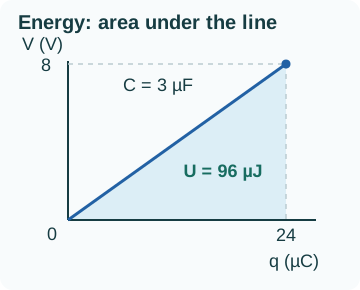
Why the factor one-half? Optional calculus
At fixed capacitance, the reversible work to transfer a small charge is . Integrating from the uncharged state gives:
Worked example 1: calculate charge, then energy
A capacitor has a voltage of . Find one plate’s charge magnitude and the stored energy.
The plates therefore carry and . Unit check: and .
Check the system: this formula gives the energy ultimately stored, not necessarily all the energy supplied by a source. A resistor may also receive energy during charging. Do not automatically equate battery work with capacitor energy.
3. Identify what the connection holds fixed
- Ideal voltage source still connected: the source fixes the potential difference. It can supply or receive charge. If changes, obtain the new charge from .
- Both terminals disconnected and insulated: charge cannot enter or leave either plate. With no leakage or other connection, each plate’s charge stays fixed. If changes, obtain the new voltage from .
- Capacitors connected to one another without a source: connected plates can exchange charge. The conserved quantity is the total signed charge on each isolated conducting group, not necessarily the charge of each plate.
“Isolated” must refer to a specific system. An entire network can be isolated from the outside while charge redistributes within it. Likewise, having no battery does not guarantee conservation of stored energy: a resistor can heat up, and an external force can move plates.
4. Recognize parallel and series connections by nodes
A node groups points joined by ideal wires, at the same equilibrium potential. Redrawing a wire without changing its connections does not change the network. The positions of the symbols on the page do not decide “series” or “parallel.”
Parallel: the same two nodes
If both capacitors connect between the same nodes a and b, they share the same directed voltage . Charges on the plates attached to node a add algebraically:
At the same voltage, the larger capacitance carries the larger charge magnitude and stores more energy. The equivalent capacitance exceeds each positive component capacitance.
Series: an isolated, neutral intermediate node
Consider a, then , then b, then , then c. Node b has no other branch. To use the “same charge” rule, the intermediate conductor, consisting of two plates and their joining wire, must also have zero initial net charge and no path to exchange charge with the outside.
For positive polarity from a to c, the inner plate of carries and the inner plate of carries . Neutrality gives , hence . Voltages add:
The equivalent capacitance is smaller than the smallest component capacitance. At equal charge, the smaller capacitance has the larger voltage and stores more energy, because and .
Important limit: if the intermediate node has conserved net charge , use the directed charges and . The equation is then , and the directed charges are unequal. Keep that constraint instead of blindly applying the usual rule. Charge does not need to cross a capacitor’s insulating gap to redistribute on the intermediate conductor.
5. Reduce a network, then recover each capacitor
Worked example 2: a parallel block in a series connection
A source maintains between A and D. Capacitors and are in parallel between A and B. This block is in series with between B and D. All capacitors start uncharged, and B has no other connection. Find the equilibrium voltages, charges and total stored energy.
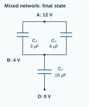
Step A: reduce the inner block first
Check the direction of the result: for the parallel step, then for the series step.
Step B: work back from the network to its branches
The block and have equal charge magnitudes. Inside the parallel block, the two capacitors instead have equal voltages:
Checks: and . At node B, the signed charges are . Neutrality is satisfied. Saying “all three are in series, so each carries 72 microcoulombs” would miss the parallel split.
Step C: check energy in two ways
The individual energies sum to the equivalent capacitor’s energy. Adding charge magnitudes over every plate would give neither the charge delivered to one network terminal nor its energy.
6. Move the plates apart: one change, two constraints
For large parallel plates in vacuum, with separation small compared with their lateral dimensions, neglect edge effects:
Here is the vacuum permittivity, approximately . Area belongs to one plate. Doubling at fixed area halves the capacitance, provided the approximation remains valid. Geometry determines the capacitance change; the connection determines what happens to , and .
Worked example 3: compare fixed charge with fixed voltage
Initially, and . Compare two separate experiments in which the plates move slowly to twice their separation. Neglect losses and kinetic-energy changes; the final capacitance is .
Experiment A: disconnect before moving
Each plate is insulated, so .
Stored energy increases by . This comes from external mechanical work against the attraction between the plates. For slow motion without losses, . Charge conservation therefore does not imply constant energy.
Experiment B: keep the 12 V source connected
Now .
Stored energy decreases by , but the external force still does positive work. The source also receives energy. Counting energy delivered by the source to the capacitor as positive:
The source receives : comes from the capacitor’s energy decrease and from external mechanical work. This balance assumes an ideal source that can absorb energy and slow movement that keeps the capacitor close to equilibrium, with negligible losses. It does not describe sudden charging through a resistor.
7. Join two capacitors: conserve charge, track energy
Two fixed-capacitance capacitors are disconnected from every source. Join their a terminals through a finite positive resistance and their b terminals together, then wait for equilibrium. Neglect external leakage, inductance, radiation and plate motion. The resistance allows transient current to decay while dissipating energy.
Initial voltages and both use a minus b as their sign convention. The a-plate group conserves its total signed charge. At equilibrium the common voltage is :
The final voltage is a capacitance-weighted average; it is the arithmetic mean only when the capacitances are equal. The b-plate group carries the opposite charge. Merely saying “the total charge of both capacitors is zero” is not enough to determine the final voltage.
Worked example 4: charge a second capacitor
A capacitor is charged to ; a capacitor is uncharged. The first capacitor’s a terminal has positive charge. Use the connection described above.
The sum recovers the a group’s initial charge. The capacitors’ energy is not conserved, however:
In this model the resistor receives by Joule heating. Charge is conserved, and total energy is conserved when the resistor’s internal energy is included. Only stored electrical energy decreases. We have assumed neither instantaneous redistribution nor a perfectly resistance-free connection.
General check on the energy difference
Subtract the final energy from the sum of the two initial energies and substitute the weighted mean for . The result is:
For positive capacitances, this is nonnegative. It vanishes when the initial directed voltages are already equal. The result concerns the source-free, fixed-geometry resistive process defined here; a different source or energy-recovery mechanism requires a different energy balance.
8. Try six graduated questions
Draw your own connection sketch and name the constraint first. Open the hint only if needed, then compare the solution’s reasoning.
Question 1: change the voltage
A linear capacitor of changes from to . Find initial and final charge magnitudes and energies. Does capacitance change?
Show a hint
Capacitance is fixed. Compare a linear dependence on voltage with a quadratic one.
Show the worked solution
Voltage triples, charge triples and energy increases ninefold. Capacitance remains .
Question 2: recognize a series connection
Two initially uncharged capacitors of and are in series across . The intermediate node is isolated and initially neutral. Find equivalent capacitance, each charge, each voltage and which capacitor stores more energy.
Show a hint
Both capacitors carry the same charge magnitude. Reduce the network before dividing the voltage.
Show the worked solution
The smaller capacitance stores three times as much energy because charge is shared. The voltages sum to 16 V.
Question 3: reconnect the same capacitances in parallel
In a fresh experiment, uncharged capacitors of and are connected in parallel across . Find equivalent capacitance, charges and the energy ratio. This is not a switching process from the state in Question 2.
Show a hint
Identify the two common nodes: each capacitor now has the full voltage.
Show the worked solution
This time, . The larger capacitance stores more energy because voltage is shared. The comparison changes with the constraint.
Question 4: modify the network in Example 2
Keep and in parallel, then put that block in series with across . All capacitors are initially uncharged, and node B has no other connection. Find all three charges and final total stored energy.
Show a hint
The parallel block and the third capacitor now have equal capacitances. That determines the voltage split.
Show the worked solution
Check node B’s neutrality and recover the same energy using the equivalent capacitance.
Question 5: diagnose a missing constraint
Someone says, “Doubling plate separation halves the energy because capacitance is halved.” In the parallel-plate model, when is this true? What happens if each plate is insulated? Explain where the energy comes from in that case.
Show a hint
Choose between the two energy expressions according to what remains fixed.
Show the worked solution
At fixed voltage, , so energy is halved. At fixed charge, , so it doubles. In the second case, for slow motion without losses, external work against the attraction supplies the energy increase. The initial conclusion omitted the connection.
Question 6: redistribute opposite signed charges
Two capacitors of have initial directed voltages and . Use the source-free resistive connection in Section 7 with fixed capacitances. Find the final voltage, final a-plate charges and energy received by the resistor.
Show a hint
Add signed a-plate charges. The negative sign describes polarity, not negative energy.
Show the worked solution
The a group’s charge remains 12 microcoulombs. Both initial capacitor energies are positive; the squares prevent a negative polarity from being treated as negative energy.
Optional workshop: how a capacitor charges and discharges
The earlier sections compare initial and final states. A resistor also determines how quickly a capacitor moves between them. Use this workshop when your electricity course includes RC transients. You need exponential functions, natural logarithms and the capacitor relation . The optional equation check uses a derivative; the examples and practice can be completed algebraically.
These are original classroom models, not instructions for building or handling electrical circuits. We use one ideal linear capacitor of constant capacitance , one resistor , and a constant ideal voltage source after each switch. Ignore leakage, inductance and the source’s internal resistance. A more complicated circuit must first justify its own model; do not insert an arbitrary resistance into these formulas.
1. Keep the voltage polarity and current reference
Call the capacitor’s marked terminals a (+) and b (−), and define . The sign marks define a measurement, not a promise that is positive. Define positive current as entering a. For the charging loop, the source raises potential by from b through the source, then current passes through R to a. Kirchhoff’s loop rule gives . With this reference, .
For discharge, remove the source and connect R across the capacitor to close the loop. Keep the same reference direction into a. This is the same equation with , so . A negative result means the actual conventional current leaves the initially positive plate. It is not an error to be erased.
Set at the switch and let . With finite R and a finite source voltage, capacitor voltage is continuous through the switch. Its current can change abruptly. Reuse the voltage reached before a switch as the initial voltage of the next interval, not zero by default.
2. Start from the final value and the initial gap
The time constant is , measured in seconds when R is in ohms and C in farads. Since , , not one second.
For in one unchanged circuit:
Check both endpoints before calculating: , , and as . At one time constant, the gap from the final value is of its initial value. The voltage has completed about 63.2% of its total change. This is 63.2% of the final voltage only when . If , the voltage falls toward the source value and the signed current is negative.
Optional equation check: the loop rule and capacitor relation give . Differentiating the proposed voltage gives ; adding v leaves . The formula also meets the initial condition, so both parts of the model are checked.
Find a target time: if a target voltage lies strictly between and , use
The logarithm contains a dimensionless number between 0 and 1. The initial value occurs at t = 0; the final value is approached but is not reached at any finite time in this ideal model when . A target outside the interval is never reached. If , voltage stays constant and the target-time formula above does not apply.
3. Worked example: charge a capacitor that is not empty
After a switch, a resistor and a capacitor are in series with a constant source. The initial capacitor voltage is , with the polarity just defined. Find the initial current, the voltage after one time constant, and when the voltage reaches .
- Convert units: .
- Use the initial gap: . The current is positive: charge enters a.
- Write the entire rule: . At , , not .
- Solve the threshold: , so .
Check at one time constant: and . The voltage is between 3 V and 12 V; the current has fallen to of its initial value. Substituting the threshold time makes the remaining gap exactly 2 V.
4. Worked example: voltage and energy have different half-times
A separate capacitor starts at . The source is removed and a resistor closes the discharge loop. Here and .
At , and . The sign follows the reference direction. The stored energy is always nonnegative:
At one time constant, , only 13.5% of the initial energy. The time to halve voltage satisfies , so . The time to halve energy satisfies , so . Energy halves sooner because it depends on the square of voltage.
With no source or other energy store in this model, the decrease in capacitor energy equals the heat dissipated in the resistor. This energy statement does not make the voltage decrease linearly.
5. Try six questions with less guidance
Keep units and sign conventions visible. Make a prediction about the starting and final states before opening each solution. The data below describe separate idealized experiments unless a switch is explicitly stated.
1. Guided: convert the time constant
An initially uncharged capacitor charges through from a 6 V source. Find , , and v after one time constant.
Show a hint
Convert microfarads and kilohms separately. In this experiment, the initial voltage is zero.
Show the explained solution
. The initial current is . At , . The corresponding current is . Check that the time constant is 200 milliseconds, not 200 seconds.
2. Diagnose: what does 63.2% describe?
For , , and , a student writes . Correct the reasoning and find the voltage.
Show a hint
How much voltage change is available between the initial and final states?
Show the explained solution
. The total change is , not 9 V. Thus . The proposed answer treats the capacitor as initially empty. At one time constant, 36.8% of the initial 6 V gap remains.
3. Independent: reach a target voltage
An initially uncharged capacitor charges through from a constant 5 V source. When does it first reach 4 V? When does it reach exactly 5 V in the ideal model?
Show a hint
Isolate the exponential before taking a natural logarithm. Distinguish an exact final value from a practical tolerance.
Show the explained solution
. From , obtain and . No finite time gives exactly 5 V because the exponential stays positive. A measurement that reads 5.00 V has finite precision; it does not establish exact equality with the ideal asymptote.
4. Infer a component from voltage data
In a source-free discharge, a capacitor falls from 12 V to 6 V in 0.600 s. Treat those data as exact for the model. Find the time constant and resistance. Is 0.600 s the time constant?
Show a hint
The measured interval is a voltage half-time. Solve first.
Show the explained solution
, so . A half-time is , not . At a full time constant, the voltage would be . Real measurements would also require uncertainty estimates.
5. Transfer: switch to a lower source voltage
A capacitor has reached 8 V. At a new t = 0, it is connected through to a constant 4 V source with the same polarity. Write v(t), find the current immediately after the switch, and determine when v = 6 V.
Show a hint
Keep the capacitor voltage continuous. The new final voltage is not zero, and the source is below the initial capacitor voltage.
Show the explained solution
The new initial voltage is 8 V and . Therefore . The initial current is , meaning actual current leaves a. For 6 V, , so . The voltage decreases toward 4 V without overshooting in this model.
6. Extend: charge and energy are not the same fraction
A capacitor starts uncharged and charges through a positive resistance from a constant 12 V source. What fraction of its final stored energy does it hold at one time constant? Over the complete charging process, compare the source’s work with the final stored energy.
Show a hint
Energy is proportional to voltage squared. For the full process, the constant source’s work is .
Show the explained solution
At one time constant, , about 40.0%, not 63.2%. The final charge is . The source supplies , while . The other 7.20 mJ is dissipated in the resistor over the full process. Changing R changes the time scale, but not these full-process energies for the same ideal constant source, initially uncharged capacitor and fixed C.
6. Check the model before choosing a formula
- Identify one unchanged circuit interval, its final voltage and its initial capacitor voltage.
- Calculate RC with consistent units. The exponent and logarithm arguments must be dimensionless.
- Check the initial and long-time limits and the signed current direction.
- Use 63.2% of the total voltage change, not automatically 63.2% of the final voltage.
- Square the voltage factor for stored energy; do not reuse the voltage half-time.
- Restart time after a switch and carry over the capacitor voltage.
For the signs behind the loop equation, return to Kirchhoff’s loop rule. For another presentation of the standard model, see OpenStax, University Physics Volume 2, §10.5: RC circuits. The examples, values and exercises in this workshop are Nablio originals. Course depth and assessments depend on your current outline.
9. Check the method before the arithmetic
- Mark nodes and voltage polarity. Do not identify connections by appearance alone.
- Write “source fixes voltage,” “each plate’s charge is fixed,” or “isolated group charge is conserved.” Specify the group.
- For series connections, justify intermediate-node neutrality before equating charges. For parallel connections, verify both common nodes.
- Reduce the network, then work back to each component. A parallel block’s total charge differs from its individual branch charges.
- Check units, summed voltages and signed charges on isolated nodes. Compare two energy calculations when possible.
- Do not impose conservation of capacitor energy alone when a source, resistor or mechanical force exchanges energy with the capacitors.
To revisit the distinction between potential and energy, see Electric Field and Potential. For voltage signs in steady resistive circuits, continue with Kirchhoff’s Laws. For the time dependence, use the optional RC charging and discharging workshop above.
10. References and course connection
Course: Concordia PHYS 205 — Electricity and Magnetism.
For further explanations of the principles, see OpenStax, University Physics, Volume 2. This guide’s problem statements, numerical choices and figures were created for Nablio; they do not reproduce course assignments or examinations.
Studying capacitance in McGill PHYS 102 or PHYS 142? Practise deciding whether charge or voltage stays fixed before calculating energy. Return to your course page for its worked examples and tutoring options.
Useful for
Work on the step you’re missing.
Tell us the subject and your preferred time. Nablio confirms the details by text or email.
Request a lesson