A magnetic field can be strong while the induced current is zero. A current can also keep the same direction while the external field changes direction. The deciding quantity is the change in magnetic flux through the loop.
Start with the four direction cases below; no calculus is needed. Then connect the picture to signed flux, angles and graph slopes. The last worked example and Question 6 are an optional calculus extension.
Before you start: know the right-hand rule for a current loop, area units and the slope of a straight line. We explain the sign convention as we go. All examples, diagrams and practice questions here are original.
1. Find the direction without calculus
Imagine a closed conducting loop lying flat on this page. You are looking straight at the front of the page. “Out of the page” means toward you; “into the page” means away from you. A dot represents the tip of an arrow coming toward you. A cross represents the tail of an arrow going away.
Keep the loop’s area and orientation fixed, with a uniform external field perpendicular to it. The direction results below describe a resistive loop with negligible self-inductance, so its current follows the induced emf. We use conventional current, the direction positive charge would move.
Lenz’s law asks what the induced current’s magnetic field would do to the change in flux. A growing outward field calls for an induced inward field. A weakening outward field calls for an induced outward field: the response resists the loss.
- External field out of the page, strengthening: induced field into the page; current clockwise.
- External field out of the page, weakening: induced field out of the page; current counterclockwise.
- External field into the page, strengthening: induced field out of the page; current counterclockwise.
- External field into the page, weakening: induced field into the page; current clockwise.
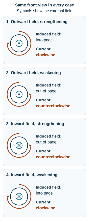
For the right-hand check, point your right thumb in the induced field direction. Your curled fingers show conventional current. Thumb toward you gives counterclockwise current; thumb away gives clockwise current.
Try saying the whole reason: “The inward flux is decreasing, so the induced field points inward to oppose that decrease; from the front, the current is clockwise.” “It opposes the field” would give the wrong result here. The response need not cancel the applied field or stop its change completely.
If the loop, its orientation and the external field all remain unchanged, there is no induced emf. An open loop can still have an induced emf, but it has no sustained circulating conduction current. The current answers in this lesson require a closed circuit.
2. Choose a normal and measure the right angle
A normal is a direction perpendicular to a surface. Choose one side of the loop as positive and draw a unit normal pointing that way. For a flat loop in a uniform magnetic field:
- is the external field’s magnitude, in teslas ().
- is the area enclosed by one turn, in square metres ().
- is the angle from the chosen normal to the field, from to .
- is the signed magnetic flux through one turn, in webers: .
The component along the normal is what counts. A field aligned with the positive normal gives ; an oppositely directed field gives . A field parallel to the plane gives zero flux, even when its magnitude is large. This simple product assumes the field is uniform over the area; a nonuniform field requires adding the contributions from different parts of the surface.
Worked example 1: 30° to the plane is 60° to the normal
A rectangular loop measures by . A uniform field makes an angle of with its plane and points toward the chosen positive side. Find the flux.
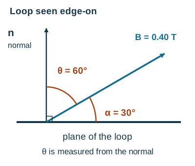
Equivalently, use for this geometry. Using gives about , because it selects the wrong component.
Check the limits: if the field lies exactly in the plane, the angle to the normal is and the flux is zero. If the field points along the positive normal, the flux is . Our answer lies between those values. A single flux value says nothing yet about an induced emf; we still need to know how the flux changes with time.
Changing a convention is different from turning the loop. If you simply replace by for the same physical loop, the signed flux reverses. If you physically rotate the loop in a fixed field, its flux can actually change with time and produce an emf.
3. Turn changing flux into a signed emf
Once the normal is chosen, use the right-hand rule to choose the positive direction around the wire. For a normal pointing toward our front observer, positive circulation is counterclockwise. Positive emf drives current that way in the resistive model; negative emf drives it clockwise.
For a coil of series-connected turns, each threaded by the same flux , Faraday’s law gives the average induced electromotive force over a time interval:
Here and are the initial and final times; and are the corresponding initial and final fluxes per turn. The bar marks a time average.
Despite its name, electromotive force (emf) is measured in volts, not newtons. It describes energy transferred per unit charge around the circuit. is the coil’s flux linkage. If a problem already gives flux linkage, do not multiply by again.
When a flux-time graph is a straight line on an interval, its slope is constant, and this calculation gives the instantaneous emf everywhere inside that interval too. For a curved graph it gives a time average; a tangent slope is needed for one instant.
- Signed flux rising: positive slope, negative emf.
- Signed flux falling: negative slope, positive emf.
- Signed flux constant: zero slope, zero emf, whether the flux is zero or nonzero.
Keep the sign until you have translated it into a direction. For magnitude alone, take . The unit check is ; a slope in gives millivolts per turn.
When can you use current = emf ÷ resistance?
Our current calculations use a closed, purely resistive circuit of total resistance , no other emf sources and negligible self-inductance and capacitive effects:
The signed current uses the same positive circulation as the emf. Self-inductance is a coil’s response to changes in its own current. If that response matters, current can lag behind the external emf or continue briefly after it becomes zero. Then is not the complete transient model. The zero-current conclusions below belong to our stated resistive approximation, not to every real coil.
In the following examples, denotes flux from the external field. We neglect the coil’s self-induced contribution when using the resistive approximation.
4. Read a piecewise flux-time graph
Worked example 2: the height gives flux; the slope gives emf
A stationary coil has turns, area per turn and total resistance . A uniform external field is perpendicular to its plane. Choose the normal out of the page and look from the front. The graph gives signed flux per turn; join the listed points with straight segments.
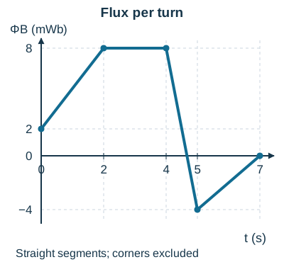
From 0 to 2 s: positive slope
The current is clockwise. Outward flux is growing, so the induced field points inward.
From 2 to 4 s: nonzero flux, zero slope
The flux stays at . Therefore and in our model. The external field is still , directed outward. Zero emf does not mean zero field.
From 4 to 5 s: negative slope through zero flux
The current is counterclockwise throughout this open interval. Initially the outward field is weakening; after flux passes through zero, an inward field is strengthening. Both changes call for an outward induced field. Passing through zero flux does not make the emf zero.
From 5 to 7 s: negative flux with positive slope
The current is about clockwise. The inward external field is weakening, so the induced field points inward. Negative flux alone does not determine the sign of the emf.
At the corners: the ideal graph has different left and right slopes at , so it has no unique derivative there. Our answers apply only inside each interval. We do not assign an instantaneous emf at those corners or at the two outer endpoints. A physical transition has a finite time scale that this simplified graph does not specify.
5. Optional calculus: a smooth changing flux
If derivatives are new, you can finish Questions 1–5 first. For this extension, review how to differentiate a polynomial. Replace the straight-segment slope with the instantaneous rate of change:
Worked example 3: zero emf at the top of the flux curve
A fixed -turn coil has area per turn and total resistance . The field is uniform and perpendicular to it. Keep outward normal and counterclockwise positive. For , the external flux per turn is:
The units on each coefficient matter: every term is a flux. Differentiate the constant, linear and quadratic terms separately:
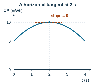
- At , the slope is . Thus and : clockwise.
- At , the slope is zero, so . But , and outward.
- At , the slope is . Thus and : counterclockwise.
Over the whole interval from 0 to 4 s, the initial and final fluxes are equal, so the average emf is zero. That does not make the emf zero throughout the interval. The clockwise and counterclockwise contributions cancel in the signed time average.
6. Check where the energy comes from
An induced current heats a resistor at a rate . Reversing current does not make that heating negative. The energy must come from somewhere: the source changing the field, mechanical work changing the geometry, or stored energy released by the wider system.
For example, when a magnet moves toward a resistive loop, the induced response resists the approach. Keeping the magnet moving requires mechanical input; if it is free to move, it can lose kinetic energy. Lenz’s sign is consistent with that energy transfer. It does not create an extra supply of energy.
Choose the system before claiming that energy is conserved within it. The loop alone can receive energy from outside, and mechanical energy alone can decrease while thermal energy increases. Use the same system-and-transfer reasoning in work, energy and momentum: choosing the method.
7. Try six graduated questions
Use a closed resistive circuit with no other emf source, negligible self-inductance and negligible capacitive effects whenever a current is requested. Unless a rotation is stated, area and orientation are fixed. All stated fields are uniform over each turn. Try the question before opening the hint or solution.
Question 1: a field that stays on
A single loop encloses . A steady field points out of the page. Choose the outward normal. Find the flux and induced emf. Would doubling this constant field necessarily give a sustained induced current?
Show a hint
Convert square centimetres to square metres. Then ask whether the flux changes after the field has become steady.
Show the full solution
, so . The field follows the normal:
This is , but it is constant. Therefore , and the induced current is zero in our model. During a change from to , an emf can occur; once the new field is steady, there is again no sustained induced current. Field magnitude and rate of change answer different questions.
Retry if you used the field instead of its change
Keep the same loop stationary in a steady field lying in its plane. What are flux and induced emf?
Answer: , so . It stays zero, hence . A field can be nonzero with zero flux, and a flux can be nonzero with zero emf.
Question 2: repair the Lenz explanation
Seen from the front, the external field points into a fixed loop and is weakening. A student says: “The current must oppose the inward field, so its field points outward and the current is counterclockwise.” Identify the error and give a correct explanation.
Show a hint
What is being lost: inward or outward flux? The induced response resists that loss.
Show the full solution
The student opposed the field rather than its change. Inward flux is decreasing in magnitude. The induced field therefore points inward, tending to maintain it. The right thumb points away from the front observer, so conventional current is clockwise. With outward normal, the negative external flux is moving toward zero: its signed slope is positive and Faraday’s minus sign gives a negative, clockwise emf.
Retry if clockwise felt absolute
A second observer looks at the same current from behind the page. What do they call its direction?
Answer: counterclockwise. The physical current did not reverse; the viewing side did. Always state the observer with a clockwise/counterclockwise answer.
Question 3: turn the loop, keep the field
A -turn coil has area per turn and total resistance . The field stays at . In , the coil rotates so the angle between its continuously chosen normal and the field increases from to . Find the initial and final fluxes, average emf and average current. During the rotation, view the loop from the tip of that normal, looking toward the loop.
Show a hint
Constant field magnitude does not guarantee constant flux. Calculate at each endpoint, then subtract final minus initial.
Show the full solution
Flux decreases as the stated angle increases. The positive emf drives counterclockwise current as viewed from the chosen normal’s tip; the observer follows that side as the coil rotates. The values are time averages. They need not be the values at every instant: even constant angular speed does not make change linearly in time.
Retry if you used the angle to the plane
The initial angle to the plane is . Can you recover the same initial flux without using ?
Answer: use . Using the cosine of the plane angle selects the wrong component.
Question 4: reverse the normal, keep the physics
For a fixed -turn coil with total resistance , the flux per turn increases linearly from to in , using an outward normal. Find emf and current from the front. Recalculate with the normal into the page, without moving anything physically.
Show a hint
Reversing the normal also reverses the right-hand-rule positive direction around the loop. Change both conventions together.
Show the full solution
With outward normal, counterclockwise is positive:
The current is clockwise from the front. With inward normal, the flux instead changes from to , giving and . But positive circulation is now clockwise from the front. The same physical current has a different signed description.
Retry if you changed only the flux sign
A calculation uses inward normal but keeps counterclockwise-from-the-front as the positive circulation. Can it use unchanged?
Answer: no. That form pairs the normal and circulation by the right-hand rule. Restore a consistent pair before interpreting the sign. A choice of notation cannot reverse a measured current.
Question 5: read slopes, including a zero crossing
A new -turn coil has total resistance . With outward normal, its flux per turn follows straight segments through , , and , with seconds and milliwebers throughout. Find emf and current at , and , seen from the front. Is the emf zero when the first segment crosses zero flux?
Show a hint
Each requested time lies inside one straight segment. Compute that segment’s slope, not its height.
Show the full solution
For , slope . Thus at , and : clockwise.
For , the flux is constant at . Thus at , .
For , slope . Thus at , and : counterclockwise.
The first segment reaches zero flux at , since when numerical values use mWb and s. Its slope is still , so the emf is still . Do not assign a unique instantaneous emf at the corners .
Retry if a negative flux made you choose positive emf
At , the flux is . What is the emf?
Answer: . The negative flux is rising toward zero, so its slope is positive. Faraday’s minus sign makes the emf negative.
Question 6: optional calculus, a turning point
A fixed -turn coil has area per turn and total resistance . Its perpendicular external field gives the following outward-signed flux per turn for :
Find emf, current and current direction at and , viewed from the front. At what interior time is the emf zero, and is the field zero then?
Show a hint
First differentiate flux. Set that derivative to zero for the zero-emf time. Use the original flux function, not its derivative, to find the field at that time.
Show the full solution
At , the slope is . Hence , and : clockwise.
At , the slope is . Hence , and : counterclockwise.
The slope vanishes at . The flux is then . Since the field is perpendicular and uniform, outward. The field is nonzero while its instantaneous rate of change, and hence the emf, is zero.
Retry if you substituted flux directly into Faraday’s law
At , the flux is . Find emf and current.
Answer: the slope is , so and , clockwise. Multiplying by the flux itself gives a flux linkage, not volts. The missing operation is differentiation with respect to time.
8. Keep a five-line solution routine
- Name the observer, choose the normal, and pair it with positive circulation.
- Identify what changes: field, area, angle, or a combination.
- Calculate flux per turn; keep the angle to the normal and the units explicit.
- Take the appropriate slope, multiply by , and use only when its assumptions hold.
- Translate the sign into a physical direction and check it with Lenz’s law.
For adjacent circuit work, practise current arrows and circuit signs. To return to your course guide, choose Dawson 203-SN2-RE, Concordia PHYS 205 or McGill PHYS 102.
If you want to work through a diagram or a difficult sign together, see electricity and magnetism tutoring.
What language is live tutoring offered in?
This lesson is available in English and French. Live tutoring is currently in English.
References and course connections
Checked 19 October 2026. The sources below support the physical principles and topic connections.
- OpenStax University Physics, volume 2, §13.1: Faraday’s law and §13.2: Lenz’s law. For the current-response limitation, see §14.4: RL circuits.
- Dawson’s current 203-SN2-RE description, Concordia’s PHYS 205 description and McGill’s 2026–27 PHYS 102 description include electromagnetic induction.
Which parts fit my course?
The direction and energy reasoning connects with Ontario SPH3U expectations F2.7 and F3.4–F3.5 in the Ontario science curriculum, printed page 193. This does not make the flux calculations or calculus extension a universal Grade 11 requirement. The college and university descriptions above establish induction as a topic; your section’s outline determines the required depth. This is focused practice, not a complete course or an official assessment guide.
Useful for
Induction practice connected with Dawson 203-SN2-RE, Concordia PHYS 205 and McGill PHYS 102. The opening direction reasoning is also useful for Ontario SPH3U. Use your section’s outline to choose the depth; the calculus extension is optional.
Work on the step you’re missing.
Tell us the subject and your preferred time. Nablio confirms the details by text or email.
Request a lesson