Electric Field vs Electric Potential: Signs, Units and Worked Examples
Distinguish electric field from potential, then track charge signs, units and separate source contributions.
Electricity and Magnetism: one-to-one online tutoring and exam preparation.
Dawson 203-SN2-RE connects electric and magnetic phenomena with circuit components and applications.
Review scientific notation, vector components, algebraic systems and energy per unit charge. Distinguish charge in coulombs, current in amperes and potential difference in volts. In a circuit, identify which points share a wire before deciding whether components are in series or parallel; the drawing’s shape is not the connection rule.
The guidance above is study preparation, not an eligibility decision. Confirm current prerequisites, restrictions and availability with Dawson College.
Check the official course catalogueTwo ideal voltage sources share a reference node assigned potential . Connect the terminal to junction through a resistor, the terminal to through a resistor, and to the reference through another resistor. Find the potential at relative to the reference and all three currents. What happens in the second source branch if its terminal potential is changed from to ?
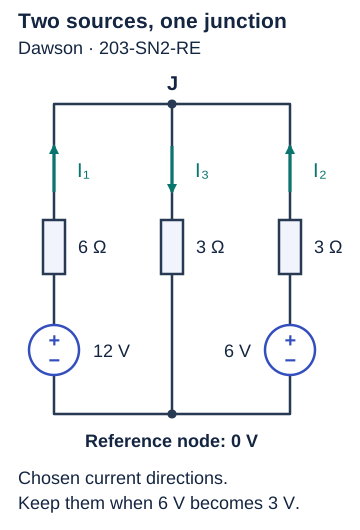
1. Define a sign convention. Let be the potential at junction , relative to the reference. Define from the first source toward , from the second source toward , and from toward the reference. Ohm’s law uses the potential at the start of each arrow minus the potential at its end: , , and . 2. Apply current conservation at the junction. Since charge does not accumulate at , . Hence . Multiplying by gives , or . Thus . 3. Compute and check the currents. Substitution gives , , and . The check confirms the junction balance. The voltage across each source-branch resistor is the difference between the potentials at its two ends. It is not the source’s full potential relative to the reference. 4. Recalculate after changing the source. Use the same arrows and replace only the second source potential. The balance becomes , giving , so . Now . Its actual direction is opposite the chosen arrow: a current of flows from toward the second source. The other currents are and , and still balances. A negative signed current is a direction result, not automatically an algebra error.
A stationary, closed coil has turns. Each turn encloses , and the circuit’s total resistance is . The coil lies in the page. A uniform external field points out of the page and increases steadily from to in . Find the current’s magnitude and direction. Let denote the signed current and the induced electromotive force (emf), measured in volts. Neglect self-inductance so the resistive approximation applies.
Choose the area normal out of the page; the corresponding positive circulation is counterclockwise. With denoting the field component along this normal, the magnetic flux through one turn is . Faraday’s law relates the emf to the change during the time interval : The field changes at , so The current is therefore clockwise.
Check with Lenz’s law: outward flux is increasing, so the induced current creates an inward field that opposes the increase. The right-hand rule gives clockwise circulation. The current opposes the change in flux, not necessarily the external field itself.
Predict the current if the outward field decreases from to in the same time, then if the field stays constant while the coil remains fixed.
For the decreasing outward field, the current is counterclockwise. If the field stays constant while the coil remains fixed, the flux does not change; the induced emf and current are zero in this resistive model.
Official practice: Dawson’s 203-SN2 sample final.
After your attempt: Dawson’s official solutions to the 203-SN2 sample final.
After the quick coil example above, go deeper into choosing a normal, reading angles and interpreting a flux graph.
Choose the viewing direction before saying clockwise or counterclockwise. The full lesson connects diagrams, Lenz’s law and the slope of flux, with six questions, hints and targeted retries. The calculus extension is labelled separately; follow your section’s methods.
Practise charging, discharging, time constants and a source change. Two worked examples and six original exercises explain signs, thresholds and the difference between voltage and energy.
Open the RC charging and discharging workshop
Dawson’s official sample-exam directory links a new-program 203-SN2-RE sample containing an RC transient problem. That supports this practice topic, not a prediction of your exam. Follow your current section outline; Nablio’s exercises do not reproduce the sample exam.
Your tutor can trace your circuit equations back to the labelled nodes and current arrows to find an inconsistent connection or sign. In field and induction problems, you can work through the direction reasoning together before checking the calculation.
Use your section’s outline to choose field, potential, capacitor, resistive-circuit and induction questions for the next exam, and check permitted tools and evaluation rules. Explain signs using the directions you chose for fields or currents, and check units. Redraw a circuit with the same connections, then verify that your node and loop equations still describe it.
We work through permitted practice and comparable problems, without completing graded assignments or exams on your behalf.
Distinguish electric field from potential, then track charge signs, units and separate source contributions.
Choose current directions, write junction and loop equations, and interpret a negative current without changing your reference arrows.
Use circuit connections to distinguish charge, voltage and stored energy in series and parallel capacitor networks.
Send your topic and preferred times. We’ll confirm whether we can help and, if so, agree on a time by text or email before payment.
Request 203-SN2-RE tutoringNablio is an independent service and is not affiliated with this institution.