Return to Sheridan MECE21469D course guide. Tutoring coverage for this course must be confirmed before booking and payment.
Stuck on a step? Text us Email us Request a lesson
Why can the two sides of one rope have different tensions? When a pulley has rotational inertia, part of the falling mass’s energy speeds up the pulley’s rotation. Separate force diagrams and one torque equation show how that changes the motion.
Start here if you can draw a force diagram and use Newton’s second law. Review connected objects and ideal pulleys first, especially the cart-and-hanging-mass question. For perpendicular lever arms, use torque and static equilibrium. Here we take the next step: the pulley can accelerate rotationally. No calculus is needed, and its moment of inertia is supplied.
1. Name the model and quantities
A cart of mass is on a level, frictionless table. A taut rope runs horizontally from the cart, over the top of a fixed pulley at the table’s right edge, then vertically down to a hanging mass . The pulley’s radius is , and its moment of inertia about its axle is . Release the system from rest. Find the acceleration, both tensions, and the speed after the hanging mass falls .
Use . The rope has negligible mass, does not stretch and does not slip on the pulley. Axle friction and air resistance are negligible. The pulley is balanced: its centre of mass lies on the fixed axle. The cart’s own rotating parts have negligible inertia. There is enough space for the cart and hanging mass to travel without hitting an obstruction.
- is the horizontal rope tension on the cart side; is the vertical rope tension on the hanging side. Both are force magnitudes, in newtons (N).
- is the common acceleration magnitude of the cart and hanging mass, in ; is their common speed, in .
- is the pulley’s angular acceleration, in ; is its angular speed, in . A radian measures rotation angle.
- , the moment of inertia, measures resistance to angular acceleration about this axle. It depends on how the pulley’s mass is distributed around the axle. Its unit is . We use the supplied , without assuming a solid-disk formula.
Choose right as positive for the cart, down as positive for the hanging mass, and clockwise as positive for the pulley. These are separate local directions; the objects do not have equal acceleration vectors.
2. Separate the two motion constraints
Fixed rope length: when the cart moves right by a distance , its horizontal rope segment shortens by . The vertical segment must lengthen by , so the hanging mass moves down by that distance. The taut, inextensible rope gives equal speed and acceleration magnitudes for these two objects.
No slipping: the rope and the pulley’s rim move together where they touch. For rotation through an angle in radians, the rim moves an arc length . With fixed , the corresponding speed and tangential-acceleration relations are:
The in the second equation is the rim’s tangential acceleration. A point on the rotating rim also has inward acceleration; that is not the cart’s acceleration. Rope length and no slipping have different jobs. Neither condition, by itself, makes the two tensions equal.
3. Draw three systems
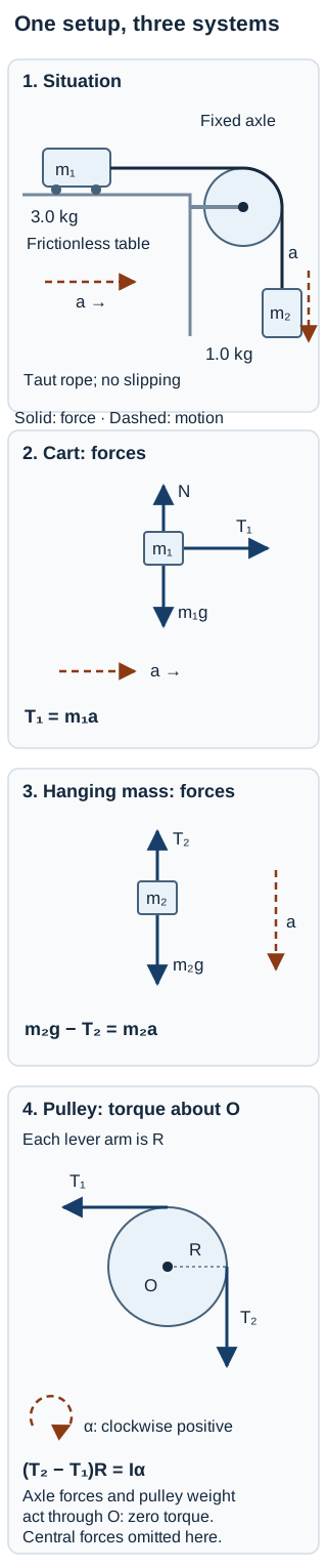
Read the diagram in words
The 3.0 kg cart is left of a fixed pulley. Its rope runs horizontally over the pulley’s top and vertically down on its right to the 1.0 kg mass. The cart accelerates right; the mass accelerates down. On the cart, table normal force N acts up, weight m₁g acts down, and T₁ acts right. On the hanging mass, T₂ acts up and m₂g acts down. In the pulley’s torque panel, T₁ acts left at the top rim, producing counterclockwise torque. T₂ acts down at the right rim, producing clockwise torque. Both perpendicular lever arms are R. The pulley’s weight and axle forces pass through the central axle O and have zero moment about O; the torque panel omits those central forces. Clockwise angular acceleration is positive. The pulley’s centre does not move.
Cart: its height does not change, so the table’s normal force balances its weight: . Horizontally, only acts. Newton’s second law gives:
Hanging mass: weight points down and tension points up. With down positive:
Pulley: choose the central axle as the torque reference. Each rope force is tangent to the rim, so its perpendicular lever arm is . The torque is clockwise; the torque is counterclockwise. For fixed-axis rotation, the net torque equals :
The axle holds the pulley’s centre in place but allows rotation. Zero centre acceleration does not imply zero angular acceleration. The central axle forces and pulley weight contribute zero torque about this axle.
Hint before solving
Use three systems. If you draw only the cart and hanging mass, which equation is missing? Write from no slipping, then substitute into the pulley equation.
4. Connect forces to torque
First eliminate angular acceleration. Divide the pulley equation by , then use :
From the cart, . From the hanging mass, . Substitute both into this tension difference:
Check the extra term before inserting it: . It has mass units and accounts for rotational inertia in this equation. The pulley’s centre stays at a fixed height, so this term does not add a falling weight to the numerator.
Return to each individual system rather than inventing an “average tension”:
The cart accelerates right and the mass down at ; the pulley accelerates clockwise. Check each equation using the results:
- Cart: , in newtons.
- Hanging mass: , in newtons.
- Pulley: , in newton metres.
Both tensions are positive, consistent with a taut rope, and , consistent with downward acceleration. No slipping is an assumption here: a friction/contact model would be needed to test whether a particular real rope and pulley can maintain it.
5. Find speed with energy
Take the cart, hanging mass, pulley and Earth as the energy system. The table normal force and fixed-axle support do no work; no slipping and negligible axle friction exclude dissipative losses in this model. The pulley’s centre and the cart remain at fixed heights. Only the hanging mass loses gravitational potential energy.
Starting from rest, a drop of gives translational kinetic energy to both masses and rotational kinetic energy to the pulley:
Use before solving:
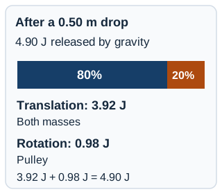
The energy totals are , and . They sum correctly. An independent constant-acceleration check gives , hence the same speed.
Energy finds speed after a displacement efficiently. It does not directly supply the two tensions; return to the force and torque equations for those.
6. Diagnose the equal-tension shortcut
A student writes, “There is only one massless rope, so .” Insert that claim into the pulley equation. It gives zero net torque, so would require . But no slipping would then require , contradicting the accelerating system.
The pulley and rope interact along their contact region. That contact lets the tension change between the two straight segments and transmits torque. A massless straight rope segment without additional tangential contact has constant tension; that statement does not make tension equal across a pulley with rotational inertia.
A second wrong shortcut adds to both the total inertia and the falling mass. Only drives this model through gravity. The pulley rotates about a fixed-height centre, so its weight does not release gravitational potential energy.
Check the ideal-pulley limit
Let approach zero while keeping the same masses and radius. Then:
This recovers the cart-and-hanging-mass answer in the ideal-pulley lesson. In the ideal limit, the rotational-inertia term and tension difference vanish. The massless-pulley model permits rotation without requiring a finite net torque.
7. Try an independent check
Keep the original masses and a drop, but replace the pulley by one with and . Keep all other assumptions. Before calculating, compare with the original value. Which of , , , and stay the same? Explain why a smaller alone is not enough to decide.
Independent-check solution
The new ratio is , exactly the original value. Therefore , , and stay the same. The smaller radius requires faster rotation for the same rope speed:
Likewise . Rotational kinetic energy remains . Translation depends on ; angular speed also depends on separately.
8. Retry with greater rotational inertia
Return to the original pulley and the original masses. Change only its moment of inertia to . From rest, find , both tensions, , and the speed after a drop. Predict whether the acceleration increases or decreases before opening the answer. Check both torque and energy.
Retry hint
The driving weight is unchanged. Which term increases in ? Keep the original three equations; do not assume either tension stays fixed.
Full retry solution
The effective-inertia term increases from to . With the same driving weight and a larger denominator, acceleration decreases:
The cart needs less force for its smaller acceleration, so falls. The hanging mass has a smaller downward net force, so rises toward its weight. The pulley torque check, using unrounded values, is:
The greater moment of inertia needs more torque even though its angular acceleration is smaller. For the speed:
Translational kinetic energy is ; rotational kinetic energy is . Their exact sum is still . More of that energy goes into rotation and less into translation. The constant-acceleration relation gives the same speed.
Transfer: can this cylinder really roll without slipping?
After the pulley examples, try this different model when rolling motion is in your outline. Allow about 15–20 extra minutes.
Optional extension: work through the rolling constraint and three retries
The pulley above rotates around a fixed centre. A rolling cylinder does two things at once: its centre moves, and it rotates around that centre. Both motions carry kinetic energy. The relation v = Rω is a constraint to check, not a rule for every round object.
Use this extension when rolling motion appears in your current course outline. Historical PHYS 131 material and Dawson's dated 203-SN1-RE sample support this topic; Concordia PHYS 204's description supports the broader rotation-and-energy connection. These sources do not establish your current assessment coverage. This is original practice.
A uniform solid cylinder has mass m = 2.0 kg, radius R = 0.10 m and moment of inertia I = ½mR² = 0.010 kg·m² about its central axis. Released from rest, it descends a fixed straight incline at θ = 30° to the horizontal. The centre drops vertically by h = 0.75 m. Take g = 9.8 m/s² and coefficient of static friction μₛ = 0.25. Model the cylinder and surface as rigid; ignore rolling resistance, air resistance and deformation losses. There is no motor or additional applied force or torque.
Predict first: does friction necessarily remove mechanical energy? Can you find the bottom speed before checking whether the surface can supply the required friction?
1. Couple translation and rotation
Draw weight mg vertically downward at the centre, the normal force N perpendicular to the incline, and static friction f uphill at contact. Take downhill translation and the corresponding rotation as positive. Here friction supplies the torque that increases the rotation. Weight and N have zero torque about the centre.
a = Rα, provided there is no slipping.
Define the dimensionless shape factor κ = I/(mR²). Substitution gives:
For this cylinder κ = ½, so a = 3.27 m/s² and f = 3.27 N uphill. N = mg cosθ = 16.97 N. The equal numerical values of a and f here are accidental: they have different units.
2. Test the assumption
Static friction adjusts as needed up to its limit. Do not set f = μₛN automatically.
Required: f ≤ μₛN, or μₛ ≥ [κ/(1 + κ)]tanθ.
The minimum coefficient is 0.192. This surface supplies at most 0.25 × 16.97 N = 4.24 N, greater than the required 3.27 N. The assumed rolling motion is consistent with the model.
3. Account for both kinetic energies
For the cylinder–Earth system, the lost gravitational potential energy becomes translational and rotational kinetic energy:
Thus v = √[2gh/(1 + κ)] = 3.13 m/s and ω = v/R = 31.3 rad/s. The 14.70 J decrease in potential energy becomes 9.80 J of translation and 4.90 J of rotation. These extra digits help check the balance; the stated data justify about two significant figures. A separate check uses the travel distance s = h/sinθ = 1.50 m: v² = 2as gives the same result.
Why is friction present without dissipating energy? In ideal rolling on a stationary surface, the point of contact is instantaneously at rest. Friction's total power is zero. In the translation-and-rotation split, its contributions are −fv and +fRω; they cancel because v = Rω. Multiplying friction by the centre's displacement belongs to the translational balance, not the total frictional work on the cylinder. Moving surfaces, slipping and deformation need a different account.
Try before opening the explanations
1. Same cylinder, but μₛ = 0.10. May you keep the speed above?
Show a hint
Hint: compare available and required friction before recalculating energy.
Show the explanation
Answer: No. The available maximum is 1.70 N, below 3.27 N. Rolling without slipping from release is inconsistent. Without a kinetic-friction model, you cannot determine a replacement acceleration or speed from the supplied information.
2. Replace the cylinder with a thin hoop having the same mass and radius, I = mR². Keep μₛ = 0.25. Does the same surface still work? If μₛ instead becomes 0.35, find the speed after the same drop.
Show a hint
Hint: changing rotational inertia changes the required friction as well as the energy split.
Show the explanation
Answer: The hoop needs μₛ ≥ ½tan30° = 0.289, so 0.25 is insufficient. With 0.35, it can roll: required f = 4.90 N, available maximum 5.94 N. Its bottom speed is √(gh) = 2.71 m/s. Translation and rotation each hold 7.35 J. It is slower than the cylinder because more energy goes into rotation for the same centre speed.
3. Does static friction always point uphill?
Show the explanation
Answer: No. It does here because it supplies the torque needed for this unpowered downhill motion. Its direction prevents relative slipping at contact. A different applied force or torque can change the direction, and some rolling motions need no friction.
Before moving on, explain the difference between a fixed pulley, a rolling body and a sliding body. State the constraint, test its feasibility, then use the energy equation that matches it.
Topic references (not current assessment guidance): McGill PHYS 131, 2022; Dawson 203-SN1-RE, 2024; Concordia PHYS 204.
9. Check your method and choose the next step
- Can you explain separately why the acceleration magnitudes match and why ?
- Can you assign each tension to the correct object and torque sign?
- Can you find both tensions after solving for acceleration?
- Does your energy equation include the pulley’s rotational energy and only the height changes that occur?
- Does the result approach the ideal-pulley answer as approaches zero?
Work through the first uncertain step with a tutor
Start with a pulley question you’re stuck on, or with how forces make a pulley rotate. Your tutor can help you draw the three diagrams, choose positive directions and write the first equations. A tutor can help identify a missing pulley equation, check the two motion constraints, and trace a sign or substitution error. Then solve a changed-inertia case yourself and explain the energy check. Ask about mechanics tutoring.
Where this topic fits
This algebra-based practice can accompany a unit on rotational dynamics. Relevant topic connections include Concordia PHYS 204, McGill PHYS 101, and mechanics 203-SN1-RE at Ahuntsic and John Abbott. Dawson 203-SN1-RE has an exact-code Summer 2026 description that includes moment of inertia. Marianopolis 203-SN1-RE has a January 2026 description covering rotational mechanics. Those dated descriptions support topic fit, not current-term offerings or assessment scope. Use your own current outline to decide when this model is relevant; this is original practice, not an institution’s exam question.
For a model with negligible pulley inertia, return to connected objects and ideal pulleys. For choosing a system and interval in other problems, use work, energy or momentum.
Useful for
Use this topic lesson when rotational dynamics is in your current outline. Dawson’s moment-of-inertia connection is supported by a Summer 2026 description; Marianopolis’s rotational-mechanics connection by a January 2026 description. These dated sources do not establish current offerings or assessment scope. Course guides retain their own coverage and availability qualifications.
Work on the step you’re missing.
Tell us the subject and your preferred time. Nablio confirms the details by text or email.
Request a lesson